Installation and Commissioning
8-28 7SA6 Manual
C53000-G1176-C156-2
1
) Factory settings for devices with power supply voltages of 24 VDC to 125 VDC
2
) Factory settings for devices with power supply voltages of 110 VDC to 250 VDC and 115 VAC
3
) Settings for devices with control voltages of 220 VDC to 250 VDC and 115 VAC
The jumpers X71, X72 and X73 on the input/output board C–I/O–1 or C–I/O–10 are
for setting the bus address and must not be changed. Table 8-12 and 8-13 lists the
jumper presettings.
The
mounting location of the PCB is illustrated in Figure 8-9 to 8-11.
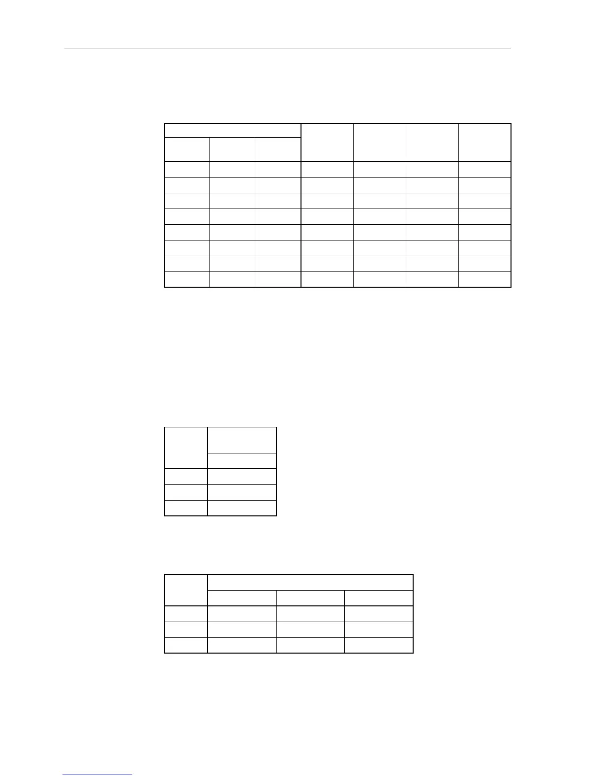
Tabelle 8-11 Jumper setting of control voltages of binary inputs BI6 to BI29 on the binary in-
put/output boards C–I/O–1 or C–I/O–10 for housing size
1
/
1
Binary Inputs
Jumper
Threshold
17 V
1
)
Threshold
73 V
2
)
Threshold
154 V
3
)
Slot 33
left
Slot 19
right
Slot 19
left
BI6 BI14 BI22 X21/X22 L M H
BI7 BI15 BI23 X23/X24 L M H
BI8 BI16 BI24 X25/X26 L M H
BI9 BI17 BI25 X27/X28 L M H
BI10 BI18 BI26 X29/X30 L M H
BI11 BI19 BI27 X31/X32 L M H
BI12 BI20 BI28 X33/X34 L M H
BI13 BI21 BI29 X35/X36 L M H
Tabelle 8-12 Jumper setting of printed circuit board addresses of binary input/output
boards C–I/O–1 or C–I/O–10 for housing size
1
/
2
Jumper
Mounting
Location
Slot 19
X71 H
X72 L
X73 H
Tabelle 8-13 Jumper setting of printed circuit board addresses of binary input/output
boards C–I/O–1 or C–I/O–10 for housing size
1
/
1
Jumper
Mounting Location
Slot 19 left Slot 19 right Slot 33 left
X71 H L H
X72 H H L
X73 H H H

 Loading...


