Installation and Commissioning
8-277SA6 Manual
C53000-G1176-C156-2
With version 7SA6∗2∗–∗N/Q/S (housing size
1
/
1
with 32 binary outputs) this goes for
binary output BO17 and BO25 (Figure 8-11, slot 19 right and slot 19 left).
Table 8-8 and table 8-9 shows the jumper settings for the contact mode.
q Check of the control voltage of the binary inputs
BI6 to BI13 (for housing size
1
/
2
) according table 8-10,
BI6 to BI29 (for housing size
1
/
1
depending on version) according Tabelle 8-11.
1
) Factory settings for devices with power supply voltages of 24 VDC to 125 VDC
2
) Factory settings for devices with power supply voltages of 110 VDC to 250 VDC and 115 VAC
3
) Settings for devices with control voltages of 220 VDC to 250 VDC and 115 VAC
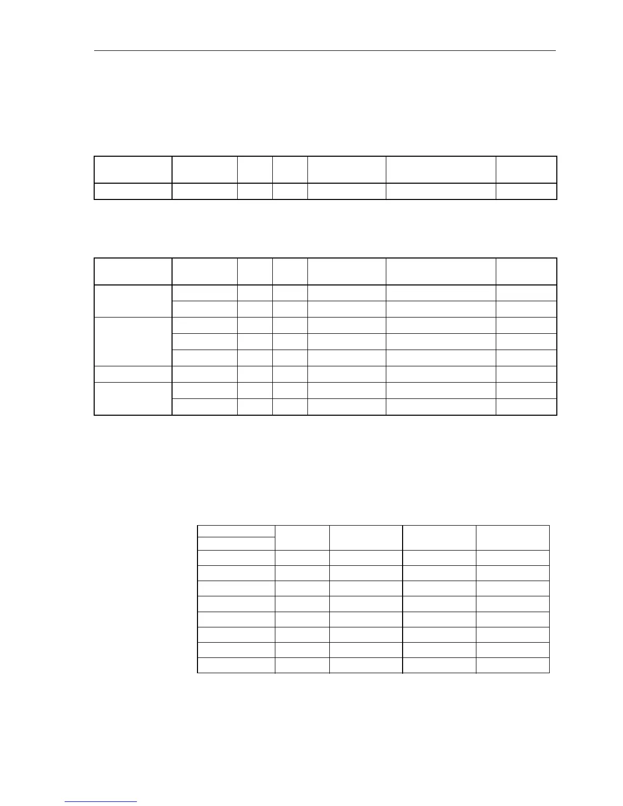
Table 8-8 Jumper setting for the contact mode of output BO9 on the input/output board C– I/O–1 (housing size
1
/
2
)
Device version
7SA6∗1∗–∗
printed circuit
board
for
Jumper
Open in quiescent
state (NO)
Closed in quiescent state
(NC)
Presetting
A/E/J slot 19 BO9 X40 1–2 2–3 1–2
Table 8-9 Jumper settings for the contact mode of outputs BO9, BO17 and BO25 on the input/output board C– I/O–1
(
housing size
1
/
1
)
Device version
7SA6∗2∗–∗
printed circuit
board
for
Jumper
Open in quiescent
state (NO)
Closed in quiescent state
(NC)
Presetting
A/E/J
slot 33 left BO9 X40 1–2 2–3 1–2
slot 19 right BO17 X40 1–2 2–3 1–2
B/F/K
slot 33 left BO9 X40 1–2 2–3 1–2
slot 19 right BO17 X40 1–2 2–3 1–2
slot 19 left BO25 X40 1–2 2–3 1–2
M/P/R slot 19 right BO17 X40 1–2 2–3 1–2
N/Q/S
slot 19 right BO17 X40 1–2 2–3 1–2
slot 19 left BO25 X40 1–2 2–3 1–2
Tabelle 8-10 Jumper settings for the Pick-up Voltages of the binary inputs BI6 through BI13
on the input/output board C–I/O–1 or C–I/O–10
for housing size
1
/
2
Binary Inputs Jumper 17 VDC
Pick-up
1
)
73 VDC
Pick-up
2
)
154 VDC
Pick-up
3
)
Slot 19
BI6 X21/X22 L M H
BI7 X23/X24 L M H
BI8 X25/X26 L M H
BI9 X27/X28 L M H
BI10 X29/X30 L M H
BI11 X31/X32 L M H
BI12 X33/X34 L M H
BI13 X35/X36 L M H

 Loading...


