Installation and Commissioning
8-32 7SA6 Manual
C53000-G1176-C156-2
Table 8-16 Jumper setting of control voltages of the binary inputs BI6 and BI7 on the
binary input/output boards C– I/O–11
1
) Factory settings for devices with power supply voltages of 24 VDC to 125 VDC
2
) Factory settings for devices with power supply voltages of 110 VDC to 220 VDC and 115 VAC
3
) Settings for devices with control voltages of 220 VDC to 250 VDC and 115 VAC
The set nominal currents of the current input transformer are checked on the input/out-
put board C–I/O–11. All jumpers must be set to the same nominal current, i.e. one
jumper for each input transformer (X61 to X64) and one common jumper X60.
However: there is no jumper X64 for the version with sensitive earth current input (in-
put transformer T8).
For normal earth current inputs the jumper X65 is plugged in position “IE” and for sen-
sitive earth current inputs in position “IEE”.
The jumpers X71, X72 and X73 on the input/output board C–I/O–11 are for setting the
bus address and must not be changed. Table 8-17 lists the jumper presettings.
Mounting location:
for housing size
1
/
3
in Figure 8-9, slot 19,
for housing size
1
/
2
in Figure 8-10, slot 33,
for housing size
1
/
1
in Figure 8-11, slot 33 right.
.
Binary Inputs
Jumper
Threshold17V
1
) Threshold 73 V
2
) Threshold 154 V
3
)
BI6 X21 L M H
BI7 X22 L M H
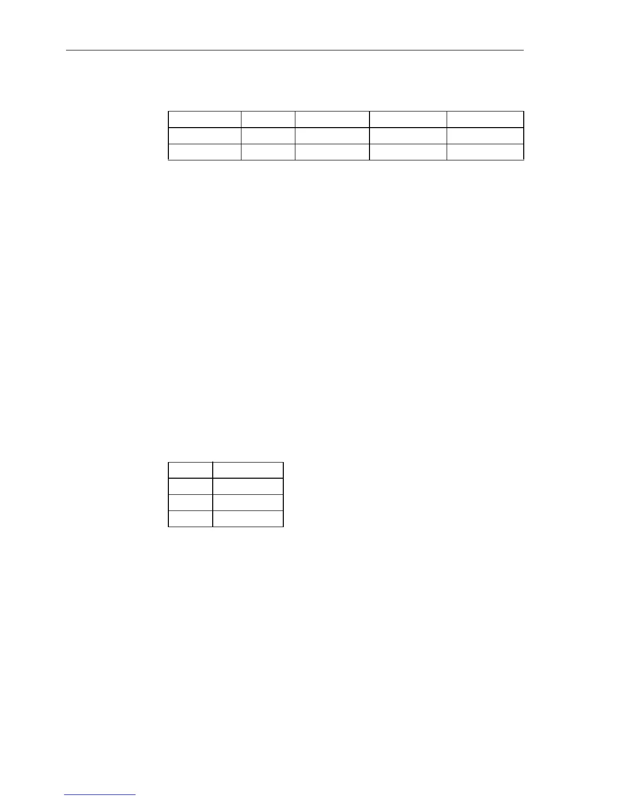
Table 8-17 Jumper setting of printed circuit board addresses of binary input/output
boards C-I/O-11
Jumper Presetting
X71 1–2 (H)
X72 1–2 (H)
X73 2–3 (L)

 Loading...


