Functions
2.6 Motor Protection
SIPROTEC, 7SJ61, Manual
C53000-G1140-C210-1, Release date 02.2008
118
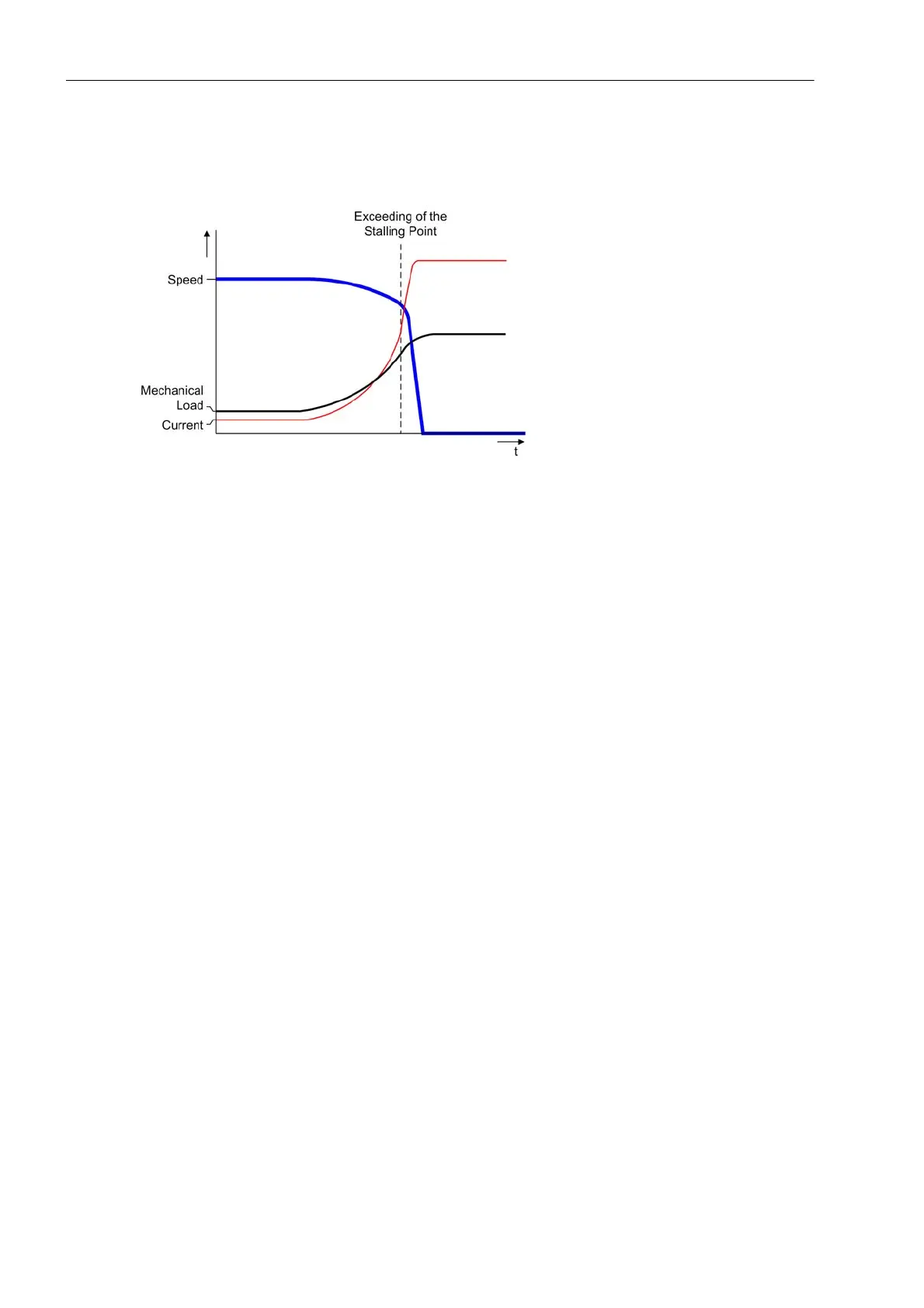
Figure 2-37 illustrates an example of a locked rotor caused by mechanical overload. It should be noted that the
current flow increases substantially as soon as the mechanical load reaches the stability limit.
Figure 2-37 Example of the time characteristic for mechanical rotor blocking
Logic
A continuous comparison of the motor current with the configured threshold values of the protection function
takes place for the purpose of detecting a locked rotor. Figure 2-38 shows the logic diagram. The threshold-
value comparison is blocked during the motor startup phase, as the startup currents usually move in a size
similar to the occurring currents when a rotor is locked.
The algorithm verifies the motor standstill according to currents and (if available) the message „>52-a“. As
soon as a current increase is applied after detection of the motor standstill, the load jam protection is tempo-
rarily blocked in order to avoid motor shutdown during the motor startup phase.
The motor is detected as being in standstill when none of the three phase currents exceeds the threshold set
via address 212 BkrClosed I MIN and the binary signal „>52-a“ is inactive. The „>52-a“ signal is only
taken into account if the binary input is allocated accordingly.

 Loading...


