Mounting and Commissioning
3.1 Mounting and Connections
SIPROTEC, 7SJ61, Manual
C53000-G1140-C210-1, Release date 02.2008
271
Power Supply
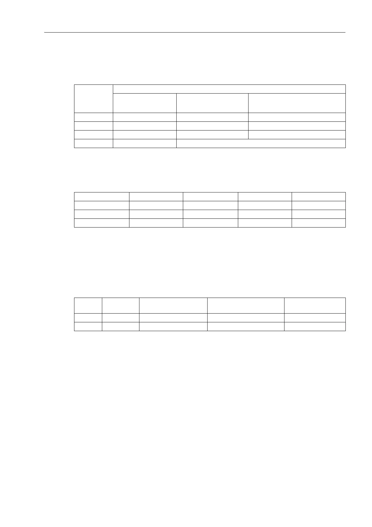
Table 3-7 Jumper settings for the nominal voltage of the integrated power supply on the processor board
A–CPU as from 7SJ61.../FF
Pickup voltages of BI1 to BI3
Table 3-8 Jumper settings for the pickup voltages of the binary inputs BI1 to BI3 on the processor board
A–CPU as from 7SJ61.../FF
1)
Factory settings for devices with rated supply voltage DC 24 to 125 V
2)
Factory settings for devices with power supply voltages of 110 VDC to 220 VDC and 115/230 VAC
Contact Mode for Binary Outputs BO1 and BO2
Table 3-9 Jumper settings for the contact mode of relays BO1 and BO2 on the processor board A–CPU
as from 7SJ61.../FF
Jumper Rated Voltage
24/48 VDC 60 to 125 VDC 110 to 250 VDC,
115 to 230VAC
X51 not used 1-2 2-3
X52 not used 1-2 and 3-4 2-3
X53 not used 1-2 2-3
not changeable interchangeable
Binary Inputs Jumper 19 VDC Pickup
1)
88 VDC Pickup
2)
176 V threshold
BI1 X21 L M H
BI2 X22 L M H
BI3 X23 L M H
for Jumper Open in quiescent state
(NO)
Closed in quiescent state
(NC)
Presetting
BO1 X41 1-2 2-3 1-2
BO2 X42 1-2 2-3 1-2

 Loading...


