Functions
2.1 General
SIPROTEC, 7SJ61, Manual
C53000-G1140-C210-1, Release date 02.2008
37
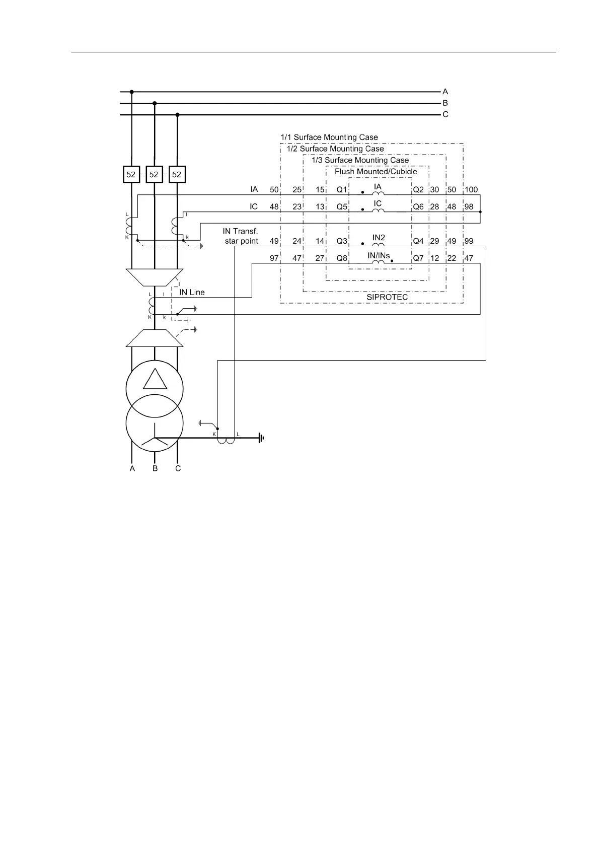
Figure 2-3 Measurement of two ground currents, example
The phase currents I
A
and I
C
must be connected to the first current input (terminals Q1, Q2) and to the third
(terminals Q5, Q6). At the fourth input (terminals Q7, Q8) the ground current I
N
or I
NS
is connected as usual, in
this case the ground current of the line. A second ground current, in this case the transformer starpoint current,
is connected to the second current input I
N2
(terminals Q3, Q4).
The settings A,G2,C,G; G->B or A,G2,C,G; G2->B must be used here. Both define the connection of a
ground current I
N2
at the second current input (terminals Q3, Q4). The settings only differ in the calculation of
I
B
. In case of A,G2,C,G; G->B, the phase current I
B
is determined by phase currents I
A
and I
C
as well as the
measured ground current I
N
or I
N sens.
at the fourth current input. In case of A,G2,C,G; G2->B, the phase
current I
B
is determined by phase currents I
A
and I
C
as well as the measured ground current I
N2
at the second
current input. The setting must be set according to system requirements.

 Loading...


