Functions
104
7SS52 V4 Manual
C53000-G1176-C182-1
5.1.3.3 Bus Couplers without Circuit Breaker
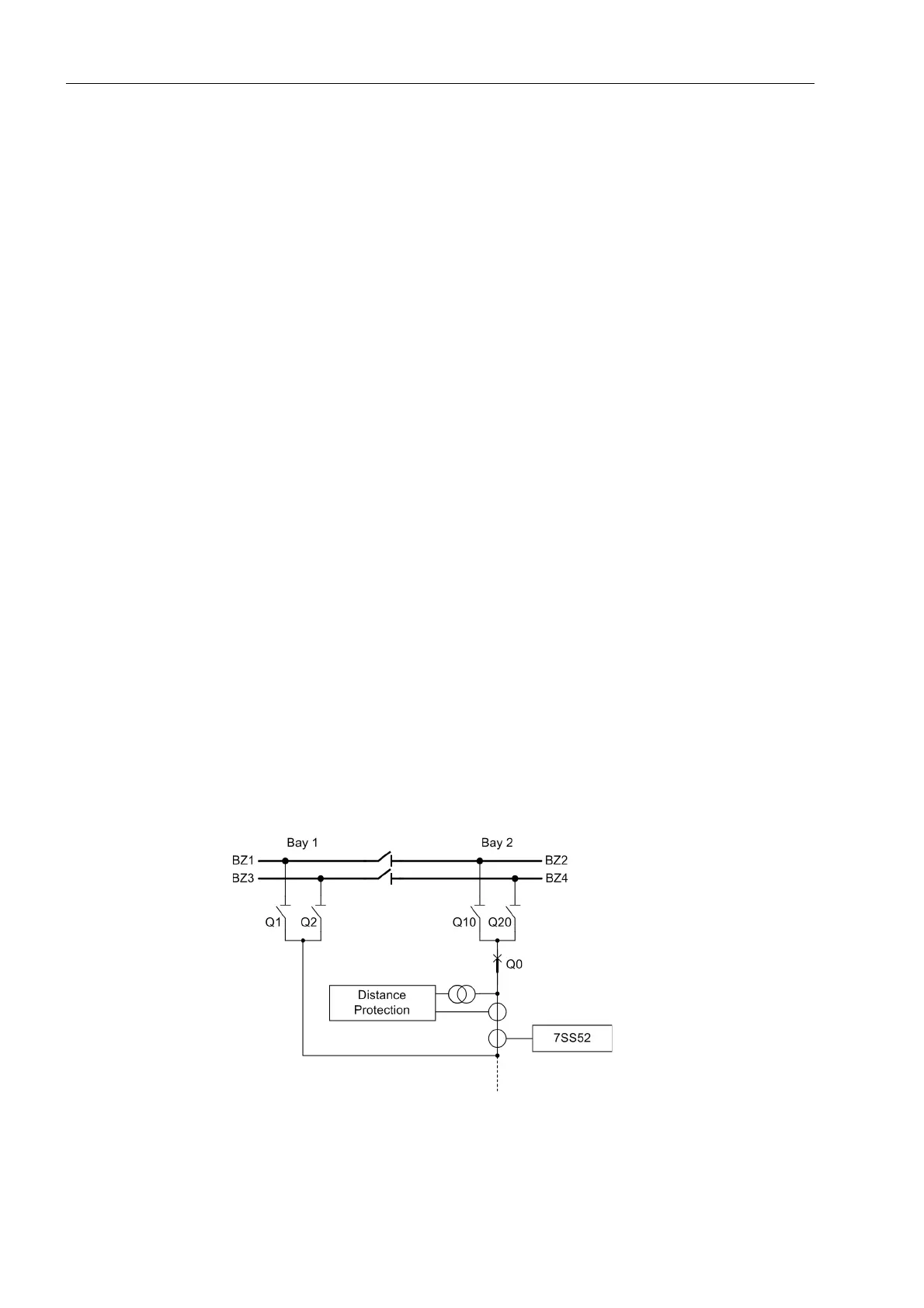
For cost reasons, bus zones are sometimes not connected by circuit breakers but by
switch-isolators (Figure 5-11, page 103), in case of auxiliary busbars for bypass oper-
ation. In order to determine nevertheless the affected zone in case of fault, the current
is measured at the coupling point. Tripping, however, must always be performed for
the entire system.
5.1.3.4 Bus Couplers with more than 5 Isolators
Each bay unit can handle up to 5 isolators. If a coupler comprises more than 5 isola-
tors, two bay units are needed even in configurations with only one current transform-
er. For the connection of the bay units, please refer to Chapter 7.1.3.3, page 249.
5.1.3.5 Combi-Coupler
The arrangement of the different switchgear elements is usally free and subject mainly
to the operational requirements. Sporadically, the switching elements such as curcuit
breaker, current transformer and isolator are used doubly, either as bus coupler or as
switchgear bay.
This special operation of the bus coupler bay is possible due to a combined bus cou-
pler parameter Combi-Coupler (XX06A/CU) in the configuration of the bay units. It is
valid for all bus coupler types with circuit breakers. In two-bay couplings, it is effective
per bay.
The presetting is No, the bus coupler acts as described in the introduction.
With the configuration Yes and in the coupled state (isolator closed on both sides),
there are also no differences.
If isolators are closed only on one side of the bus coupler in this configuration, the cur-
rent is assigned to the corresponding busbar and the check zone. The bus coupler be-
haves like a switchgear bay. The protected zone ends behind the current transformer.
An extension of the protected zone or an increased selectivity can be achieved via the
end fault protection.
Figure 5-12 Operation of a bus coupler as switchgear bay

 Loading...


