Connection Method
25
7SS52 V4 Manual
C53000-G1176-C182-1
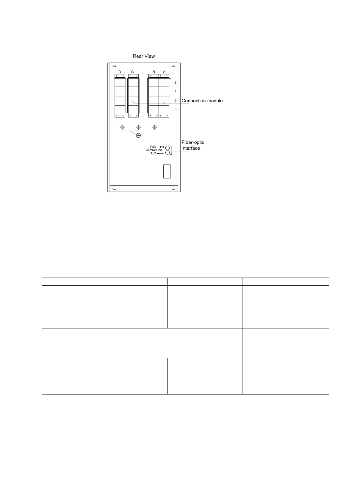
7SS525 bay unit
Panel flush
mounting or
cubicle mounting
Figure 2-9 Device connections on bay unit 7SS525
2.3.2 Device Connections
Tabelle 2-1 Overview of device connections
Variant Current connections Voltage connections FO connections
Central unit Screw connection
for max. 1.5 mm²
and
Double leaf-spring-crimp con-
tact for max. 1.5 mm²
Integrated
ST connector for
FO connection,
glass fiber 62.5/125 µm
FO duplex outdoor cable or
FO duplex indoor cable
Bay unit
Panel surface
mounting
Screw-type terminals
for stranded wires with max. 4 mm²
or
for solid wires with max. 7 mm²
Integrated
ST connector for
FO connection,
glass fiber 62.5/125 µm
Bay unit
Panel flush mount-
ing or
cubicle mounting
Screw connection
for max. 4 mm²
and
Double leaf-spring-crimp
contact for max. 2.5 mm²
Screw connection
for max. 1.5 mm²
and
Double leaf-spring-crimp con-
tact for max. 1.5 mm²
Integrated
ST connector for
FO connection,
glass fiber 62.5/125 µm

 Loading...


