Marshalling
67
7SS52 V4 Manual
C53000-G1176-C182-1
The allocable signalling functions can be looked up in Chapter A.10, page 372 and
match the signal relay functions.
Trip relay The bay unit features 5 trip relays which are labelled TRIP RELAY 1 to 5.
Several functions can be marshalled to each trip relay. Also each logic function can be
allocated to several trip relays.
The trip relays are preferably designed for the output of the TRIP command and of the
transfer trip command. Depending on the plant specification and requirements they
can also be used as additional signal relays.
The default functions of the device upon delivery are comprised in Table A-28, page
389 and Table A-32, page 392.
The functions stated in Chapter A.10, page 372 can also be marshalled to the trip re-
lays.
4.5.2.2 Marshalling
Unlike the central unit the bay units are marshalled via dialog boxes and not via a con-
figuration matrix.
To perform allocations for a bay unit you must:
Open the bay unit in DIGSI Manager.
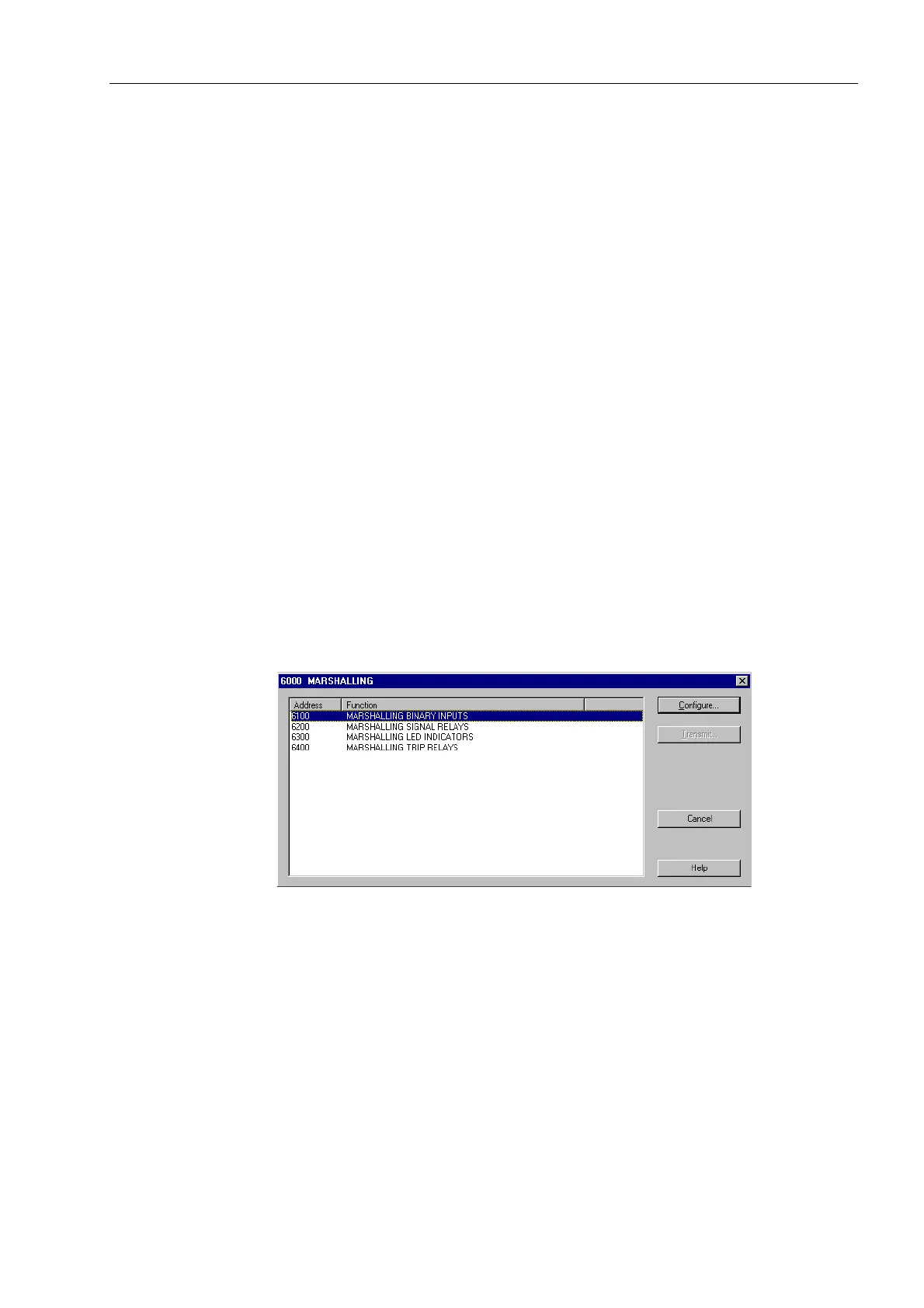
Open the dialog box Marshalling.
Figure 4-18 Marshalling the bay units - the dialog box Marshalling
In this dialog box you will first select a group of physical components, for example
binary inputs. For this purpose, select the corresponding designation in the Func-
tion column. Subsequently click Configure.... A second dialog box opens. It shows
the names of all individual components of the selected group.

 Loading...


