Home
Siemens
Controller
SIRIUS 3RW52
Equipment Manual
Page 223
Siemens SIRIUS 3RW52 - Page 223
258 pages
Manual
To Next Page
To Next Page
To Previous Page
To Previous Page
Loading...
Examp
le c
ircuit
s
A.2
Con
tr
ol
ci
rc
uit
con
ne
ct
ion
SIRIU
S 3RW5
2 So
ft Sta
rter
Equipm
ent
Manua
l
,
04/2020
,
A5E3
563
0451
002A/R
S
-
AE/00
5
223
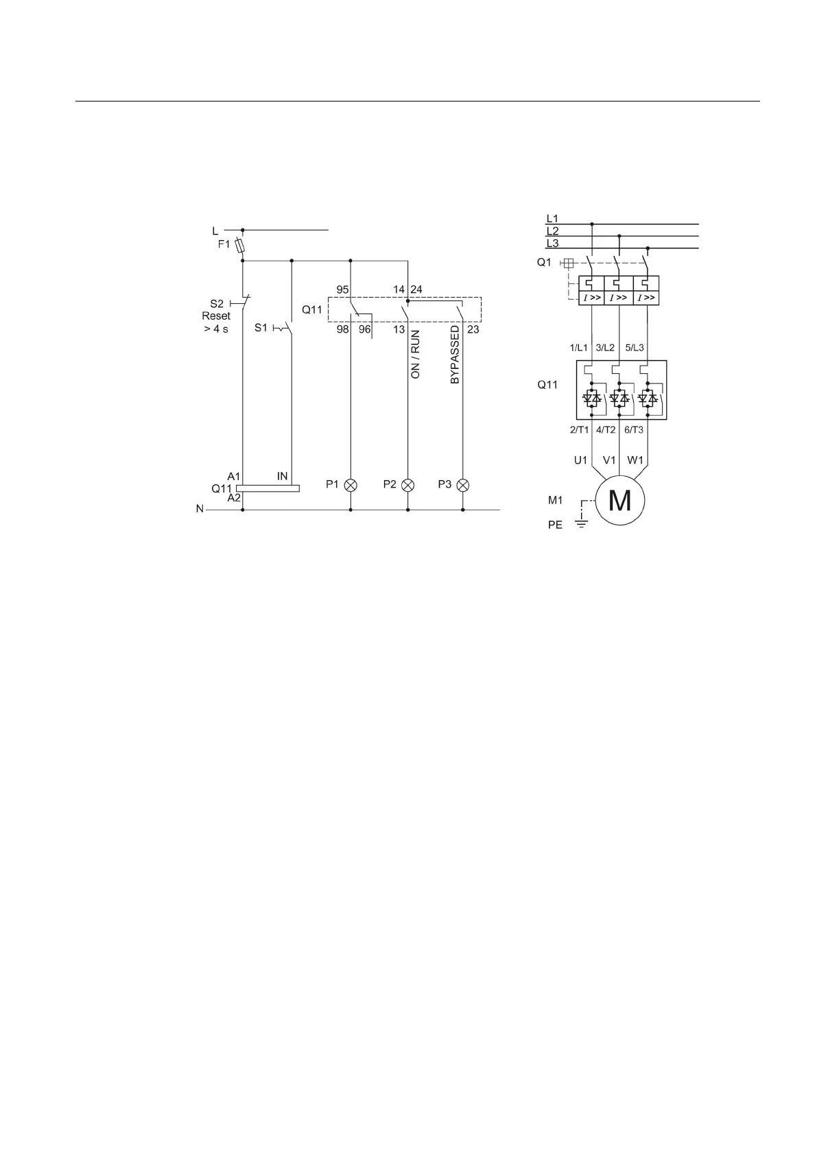
Wiring of control circuit
for control by swi
tch
The example
shows the 3RW5
2 soft start
er in the inl
ine c
ircui
t.
F1
Fuse
S1
Switch: Start/stop
S2
Pushbutton: Reset >
4 s
Q1
Motor
star
ter p
rot
ector
Q11
3RW52 soft
s
tarter
M1
Motor
P1
Indicator li
ght
P2
Indicator light
P3
Indicator light
PE
Protective conductor
222
224
Table of Contents
Main Page
Default Chapter
3
Table of Contents
3
1 Siemens Industry Online Support
9
Support Request
12
Additional Documentation
13
2 Safety Information
15
ESD Guidelines
15
Five Safety Rules for Working in or on Electrical Systems
17
Reactive Power Compensation
18
Electromagnetic Compatibility (EMC) According to IEC 60947-4-1
19
Security Information
20
Protection against Unauthorized Actuation
21
Firmware Update
22
Recycling and Disposal
23
3 Description
25
Target Group
25
History
26
Device Design
27
Operating Principle
28
Access Options for the 3RW52 Soft Starter
30
Operating Modes and Master Control Function
32
Operating Modes
32
Sets the Operating Mode
35
Device Versions
40
Areas of Application / Load Types
42
Selection of the Soft Starter Using the Simulation Tool for Soft Starters
43
Structure of the Article Number
44
Accessories for 3RW52 Soft Starter
46
3.11 Accessories
48
3RW5 Communication Module
48
SIRIUS Soft Starter es (TIA Portal)
49
3Rw5 Hmi
51
4 Mounting and Dismantling
53
Installing the 3RW52 Soft Starter
53
Mounting the Fan Cover
54
Mounting the 3RW52 Soft Starter on a Level Surface
56
Installing, Mounting and Removing the 3RW5 HMI
58
Installing the Standard 3RW5 HMI in 3RW52 Soft Starter
58
Removing Standard 3RW5 HMI
60
Installing the High Feature 3RW5 HMI in the 3RW52 Soft Starter
61
Removing the High Feature 3RW5 HMI
62
Installing the Standard 3RW5 HMI into the Control Cabinet Door
63
Installing the High Feature 3RW5 HMI in the Control Cabinet Door
67
Installing the Standard 3RW5 HMI on a Flat Surface
71
Installing the High Feature 3RW5 HMI on a Flat Surface
73
Cut out the Hinged Cover for 3RW5 HMI
75
Replacing the Hinged Cover of the 3RW52 Soft Starter
76
5 Wiring
77
Connections
77
Overview of All Connections
77
State Diagrams of the Inputs and Outputs
79
Connecting the 3RW52 Soft Starter
81
Connect the 3RW52 Soft Starter to the Main Circuit Connection (Line Side / Motor Side)
82
Mounting Terminal Covers on Main Circuit Connections
84
Replacement of the Box Terminal Blocks with Size 2
86
Connecting the Control Terminals (Screw Terminals)
88
Disconnecting the Control Current Form the Screw-Type Terminals
89
Connecting the Control Terminals (Spring-Type Terminals)
90
Disconnecting the Control Current from the Spring-Loaded Terminals
91
Replacing the Control Terminals
92
Installing the Cover for the Control Cable Duct
94
Removing the Cover of the Control Cable Duct
95
6 Parameter Assignment
97
Setting Elements on the 3RW52 Soft Starter
97
Overview of Parameters
100
Suggested Settings
101
Parameterizing the 3RW52 Soft Starter
102
Setting RESET MODE and Soft Torque
103
Reset Mode
105
Parameterize Output 13, 14 (Output Signal on or RUN)
106
Parameterize the Response to Bus Errors and Output 13, 14 (on / RUN)
108
Design and Operator Controls of the High Feature 3RW5 HMI
111
Menu of the 3RW5 HMI High Feature
113
Parameterize Analog Output AQ Via the 3RW5 HMI High Feature
121
Parameterizing the High Feature 3RW5 HMI
124
Parameterize 3RW5 HMI High Feature Serially / Identically
126
7 Commissioning
127
Commissioning the 3RW52 Soft Starter
127
Sealing the 3RW52 Soft Starter
128
First Commissioning of the High Feature 3RW5 HMI
129
8 Functions
131
Soft Starting
131
Current Limiting Function
134
Soft Stopping
136
Motor Protection
137
Electronic Motor Overload Protection
137
Thermistor Motor Protection with Temperature Sensor (Optional)
139
Intrinsic Device Protection
140
Soft Torque
141
Functions under "Additional Parameters
143
Test with Small Load
143
Test Mode
144
Response to Bus Errors / Control Via Digital Input
147
Standard 3RW5 HMI
149
Design of the Standard 3RW5 HMI
149
Standard 3RW5 HMI Menu
151
High Feature 3RW5 HMI
154
Monitoring
154
Monitoring the Measured Values of the 3RW52 Soft Starter with the 3RW5 HMI High Feature
154
Graphic Display of Measured Values on the 3RW5 HMI High Feature
156
Monitoring the Process Image of the 3RW52 Soft Starter with the High Feature 3RW5 HMI
158
Overview
160
Local Access Protection (PIN)
162
Define PIN
163
Change PIN
164
Delete PIN
165
Micro SD Card
166
Reloading a Language for the High Feature 3RW5 HMI
168
9 Messages and Diagnostics
169
Diagnostics Options
169
LED Display
170
Overview of the Device Leds of the 3RW52 Soft Starter
170
Status and Error Displays
171
State / Overload Led
172
Overview of Leds on Standard 3RW5 HMI
173
Overview of Leds on High Feature 3RW5 HMI
174
Warnings and Remedial Actions of the 3RW52 Soft Starter
175
Faults and Remedial Actions of the 3RW52 Soft Starter
176
Faults and Remedial Actions of the 3RW5 HMI High Feature
181
Diagnostics of the 3RW52 Soft Starter with the 3RW5 HMI High Feature
182
Execute HMI Diagnostics with the 3RW5 HMI High Feature
185
Performing Diagnostics of the 3RW5 Communication Module with the 3RW5 HMI High Feature
186
Self-Test (User-Test)
187
Logbooks
191
Save Service Data to Micro SD Card
192
10 Maintenance and Servicing
195
Maintenance and Repairs
195
Firmware Update
196
Performing Firmware Update with Micro SD Card (3RW5 HMI High Feature)
198
Restore Factory Setting
199
Restoring the Factory Settings Via High Feature 3RW5 HMI
201
Restoring the Factory Settings with the Master RESET Button Via 3RW5 HMI High Feature
202
Restoring the Factory Settings with the MODE and RESET / TEST Keys
203
Device Change" Function
204
Device Change with Micro SD Card on the 3RW5 HMI High Feature
205
Device Change with SIRIUS Soft Starter es (TIA Portal)
206
11 Technical Specifications
207
Technical Data in Siemens Industry Online Support
207
12 Dimension Drawings
209
Cax Data
209
Drilling Pattern for 3RW5 HMI Standard
210
Drilling Pattern for 3RW5 HMI High Feature
211
13 Circuit Diagrams
213
Cax Data
213
Example Circuits
215
Main Circuit Connection
215
Feeder Assembly, Type of Coordination 1 Fuseless
215
Feeder Assembly, Type of Coordination 1 with Fuses
216
Feeder Assembly, Type of Coordination 2
217
Inside-Delta Circuit
218
Control Circuit Connection
221
Control by Pushbutton
221
Control by Switch
222
Switching with Supply Voltage (Control Supply Voltage)
224
Control by PLC
226
Actuation of a Line Contactor
228
Wiring for Remote RESET
230
Connecting the Temperature Sensor
231
Connecting the Evaluation Unit to the Analog Output
232
Special Applications
233
Reversing Circuit
233
Controlling a Motor with a Magnetic Parking Brake
235
EMERGENCY STOP Shutdown to SIL 1 or PL C with a 3SK1 Safety Relay
237
EMERGENCY STOP Shutdown to SIL 3 or PL E with a 3SK1 Safety Relay
242
Contactor for Emergency Start
247
Third-Party Software
249
Information about Third-Party Software
249
Glossary
253
Index
255
Other manuals for Siemens SIRIUS 3RW52
Manual
198 pages
Related product manuals
Siemens SIRIUS 3RW55
238 pages
Siemens SIRIUS 3RW50
238 pages
Siemens SIRIUS 3RW5 series
106 pages
Siemens PROFINET SIRIUS 3RW5
214 pages
Siemens SIRIUS 3RW40
204 pages
Siemens SIRIUS 3RW44
262 pages
Siemens SIRIUS 3RW30
204 pages
Siemens SIRIUS 3RW40 2
32 pages
Siemens Sirius 3RW44 V.6.2
34 pages
Siemens SIRIUS 3RW44 2 Series
46 pages
Siemens SIRIUS 3RW40 24 Series
32 pages
Siemens SIRIUS 3RM1
196 pages

 Loading...


