Description of SISTORE MX / MX DVD
19
Siemens Building Technologies
Fire Safety & Security Products 02.2009
EN
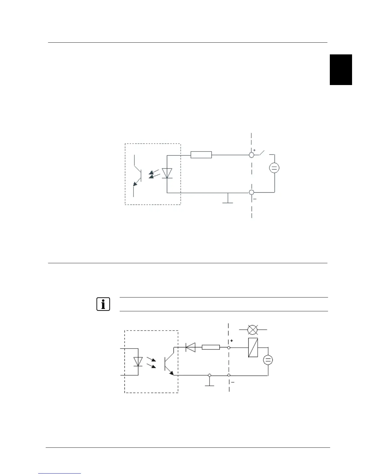
6.2.3 Trigger and digital inputs
The HVR is equipped with optocoupler that run the TTL-compatible trigger inputs of
the SISTORE MX via optocoupler and enable the switching of signal levels up to
24 V.
The inputs of the optocoupler are designed for a voltage range of 5 to 24 V.
With the SISTORE MX there are 32 trigger inputs and 8 digital inputs available.
These trigger inputs are edge triggered. The trigger edge which is to initiate a
trigger event can be selected with the software (SISTORE RemoteView and
SISTORE MX).
Input circuitry of the optocoupler
Optokoppler
U1
1K2
R
V
5 - 24 V
Digital In
Fig. 4 Optocoupler – input circuitry (example of pin assignment)
The 8 digital inputs can be used to control external events.
6.2.4 Digital outputs
The outputs ground a connected consumer. All outputs can handle a maximum
current of 50 mA. Fusing of the outputs is implemented with reversible fuses. All
outputs are short circuit proof.
If inductive consumers are connected, we recommend using appropriate protective circuits.
U1
Optokoppler
D1
F1
50 mA
Digital Out
5 - 24 V
Fig. 5 Optocoupler – output circuitry (example of pin assignment)
 Loading...