Installation
29
Siemens Building Technologies
Fire Safety & Security Products 02.2009
EN
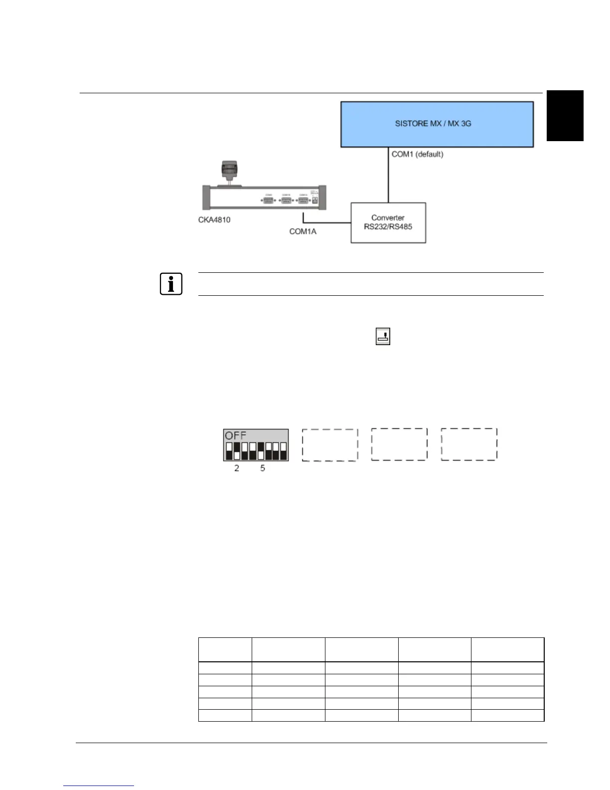
8.4.1 Connecting control panel CKA4810
8.4.1.1 SISTORE unit
Fig. 13 SISTORE unit – CKA4810 system overview
For a more detailed description of the connections please refer to Section
83H6 84HDescription of SISTORE
MX / MX DVD or Section
85H7 86HDescription of SISTORE MX 3G / MX 3G DVD.
Prerequisite:
z The CKA driver is installed and the icon is displayed in the task bar. See
Section
87H9.3 88HSubsequent installation of software components.
1. Connect the converter between the control panel CKA4810 and the SISTORE
unit (see
89HFig. 13). See Section 90H4 91HDetails for ordering92H.
2. Configure the COM1A connection on the control panel for use as an RS232
interface.
Further information on this can be found in the instruction manuals for the
control panel CKA4810 and the converter.
3. Start the SISTORE MX application software.
4. Switch to configuration mode.
5. Select the System tab.
6. Mark the checkbox CCTV keyboard. Further information on this can be found
in the SISTORE MX Configuration Manual.
7. Click Apply.
Î The interface for the control panel is enabled.
Connections
Signal SISTORE unit
9-pin Sub-D socket
Converter Converter
25-pin Sub-D
CKA4810
9-pin Sub-D plug
A (Rx/Tx +) 2 T +
B (Rx/Tx -) 3 T -
GND 5 7 5
RXD 3 2
TXD 2 3
 Loading...