Design and function
2015-09-07 / DIS 113_58300000171499_ara_en_c Copyright by BSH Hausgeräte GmbH Page 19 of 65
3.10 Condensate tank
3.10.1 Design
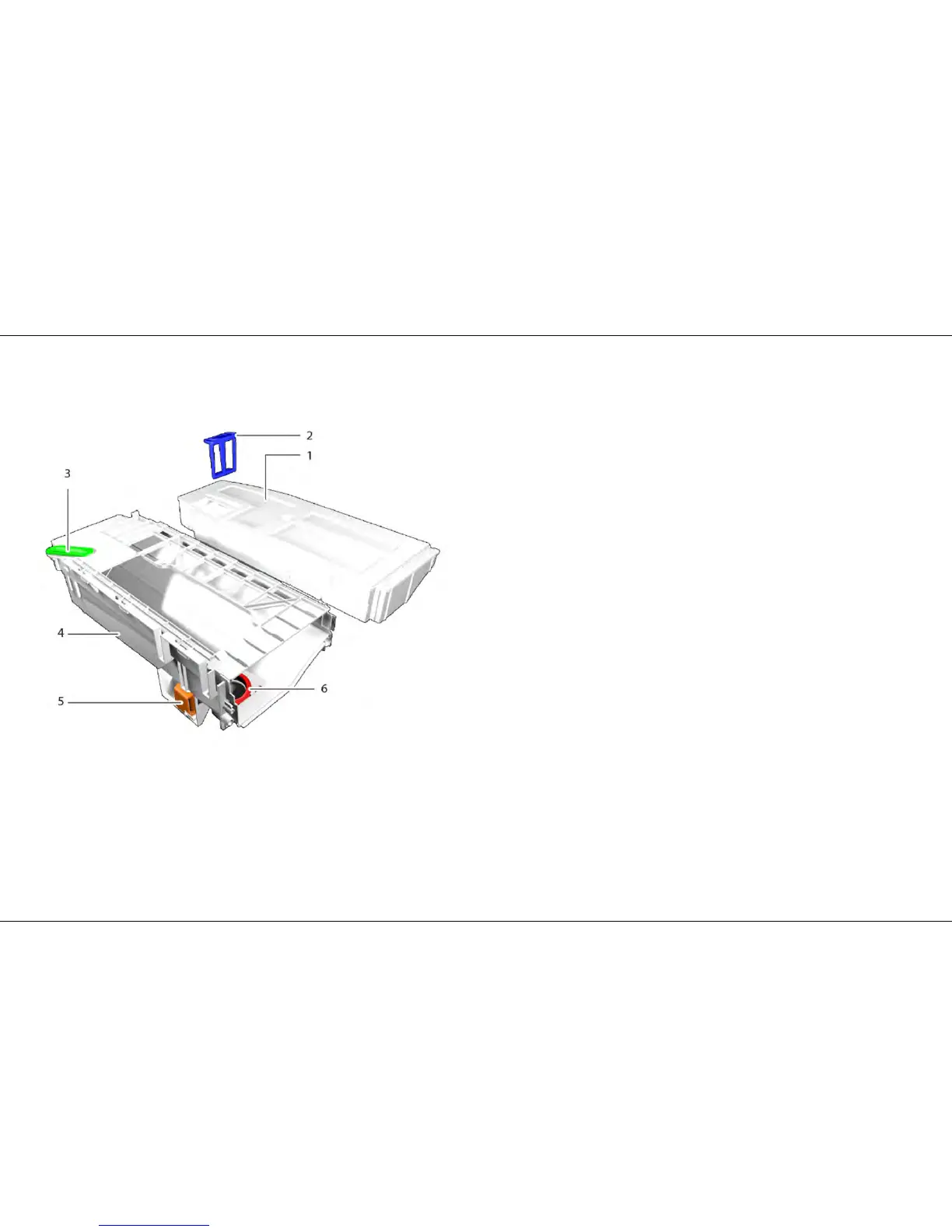
Graphic 10:Components of the condensate tank
1 Flush chamber and storage chamber 4 Shell
2 Filter 5 Flush valve
3 Nozzle 6 Flush opening
3.10.2 Function
The condensate pump in the base tray pumps the condensate through the filter
into the condensate tank. The lint in the condensate is trapped in the filter. The
filter is normally cleaned by the draining of the condensate tank, but can also
be removed manually for cleaning. The tank is divided into two sections: one for
cleaned condensate and one for unfiltered condensate (max. 4.8 l). The cleaned
condensate is conveyed through the flush valve and the flush opening via a fall
pipe to the inlet of the heat pump in order to flush away the lint.