Sierra Wireless FX30 User Guide
Rev 4 March 2019 24 41110030
• Pin 3 (On/Off)—Connect to an on/off switch
Pin 3 must be connected.
• Optional—I/O 1, I/O 2, and I/O 3
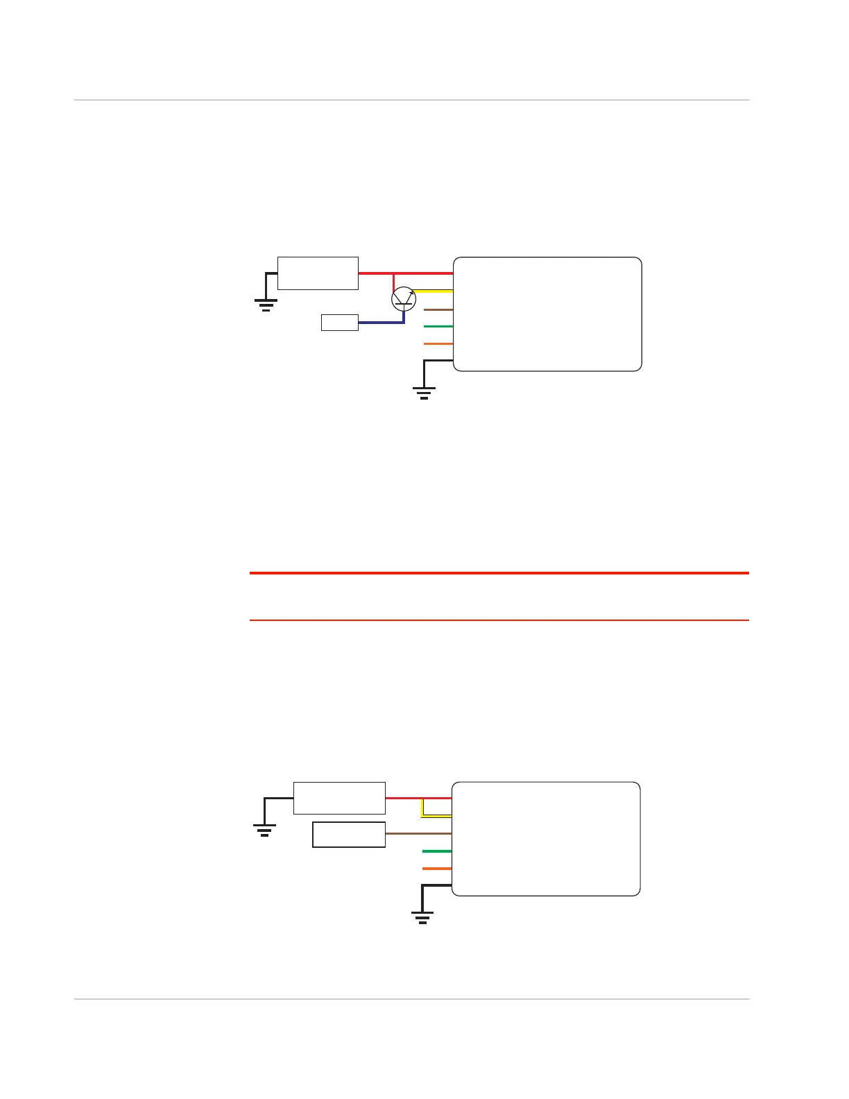
An On/Off installation may also use a sensor with an open-collector NPN or PNP
transistor. The transistor is the switch to turn the FX30 on or off, as shown in
Figure 2-17.
Figure 2-17: On/Off Installation (with sensor and NPN transistor switch)
• Pin 1 (Power)—Use the red wire in the DC cable to connect Pin 1 to the
power source and the collector pin of the transistor.
• Pin 2 (Ground)—Use the black wire in the DC cable to connect Pin 2 to
ground. See also Step 2—Mount and Ground the FX30 Chassis on page 12.
• Pin 3 (On/Off)—Connect to the emitter pin of the transistor
Pin 3 must be connected.
• Optional—I/O 1, I/O 2, and I/O 3
Note: See Table D-1, FX30 Hardware Feature to Linux Interface Mapping, on page 74 for
the radio module GPIO and Linux interface mapping of pin 3, I/O 1, I/O 2, and I/O 3.
Installation with I/O Input Triggered by Standby Mode
If you have an installation where you want to use the I/O to monitor an external
device such as a motion detector or gate sensor, refer to Figure 2-18. If desired,
you can use Legato to program the I/O line to wake the gateway from ultra low
power mode for a specific length of time.
Figure 2-18: Fixed Installation with I/O
Gateway
Power
On/Off
Ground
DC power source
1
3
2
I/O1
I/O2
I/O3
Sensor
NPN
FX30
DC power source
2 Ground
I/O 3
I/O 2
I/O 1
1 Power
3 On/Off
Sensor
DC power source
Gateway
Power
On/Off
Ground
Motion sensor
1
3
2
I/O1
I/O2
I/O3
FX30
DC power source
2 Ground
I/O 3
I/O 2
I/O 1
1 Power
3 On/Off
Motion sensor