Installation and Startup
Rev 4 March 2019 23 41110030
Wiring Diagrams
In the following diagrams, FX30 refers to either FX30 and FX30S.
Always On Installation
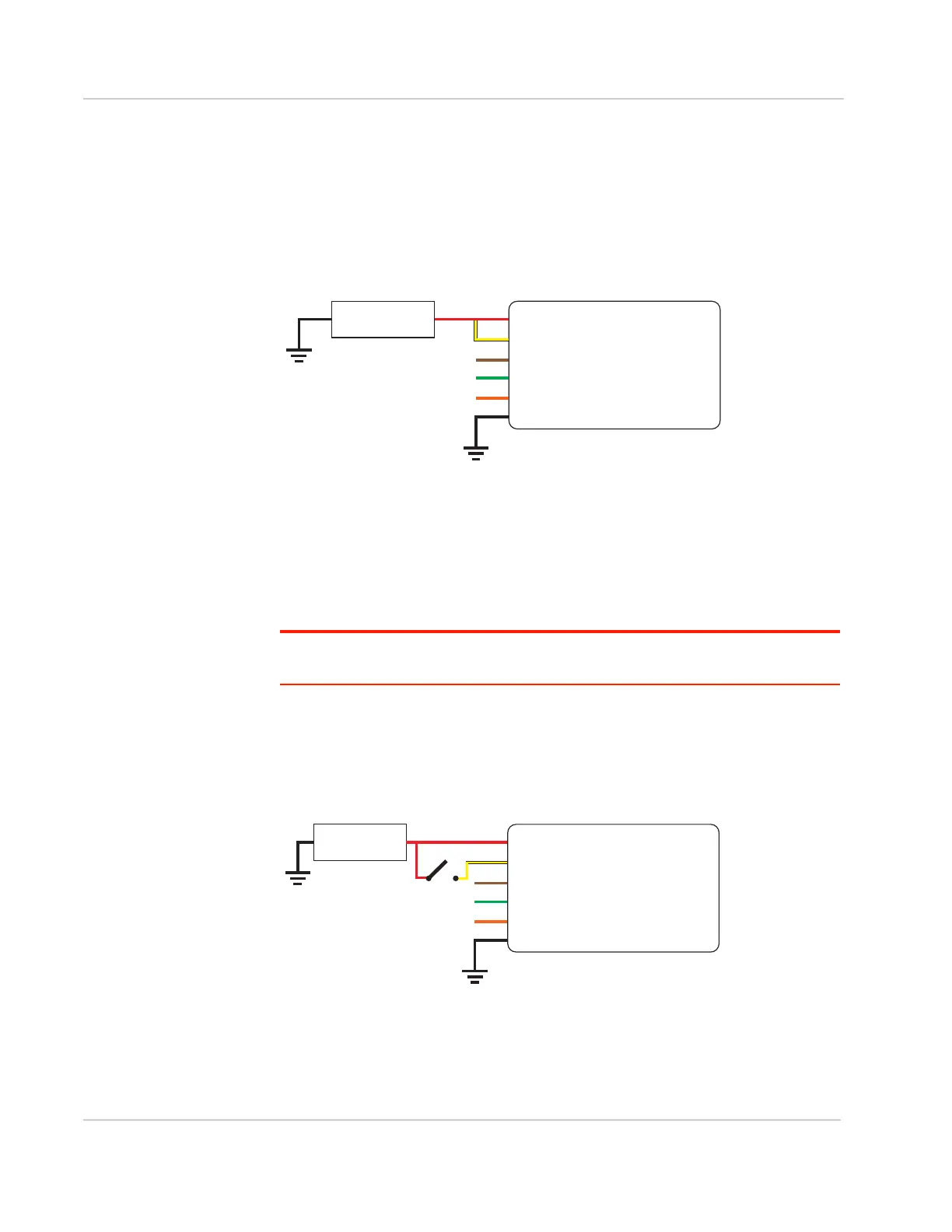
For an Always On application, connect the wires as shown in Figure 2-15.
Figure 2-15: Always on installation
• Pin 1 (Power)—Use the red wire in the DC cable to connect Pin 1 to the
power source.
• Pin 2 (Ground)—Use the black wire in the DC cable to connect Pin 2 to
ground. See also Step 2—Mount and Ground the FX30 Chassis on page 12.
• Pin 3 (On/Off)—Connected to power
• Optional—I/O 1, I/O 2, and I/O 3
Note: See Table D-1, FX30 Hardware Feature to Linux Interface Mapping, on page 74 for
the radio module GPIO and Linux interface mapping of pin 3, I/O 1, I/O 2, and I/O 3.
On/Off Installation
For an On/Off application, connect the wires as shown in Figure 2-16 or
Figure 2-17.
Figure 2-16: On/Off Installation with switch
• Pin 1 (Power)—Use the red wire in the DC cable to connect Pin 1 to the
power source.
• Pin 2 (Ground)—Use the black wire in the DC cable to connect Pin 2 to
ground. See also Step 2—Mount and Ground the FX30 Chassis on page 12.
Gateway
Power
On/Off
Ground
DC power source
1
3
2
I/O1
I/O2
I/O3
FX30
DC power source
2 Ground
I/O 3
I/O 2
I/O 1
1 Power
3 On/Off
On/Off switch
DC power source
Gateway
Power
On/Off
Ground
1
3
2
I/O1
I/O2
I/O3
FX30
DC power source
2 Ground
I/O 3
I/O 2
I/O 1
1 Power
3 On/Off
On/Off switch