Levels of System Control
007-5832-002 29
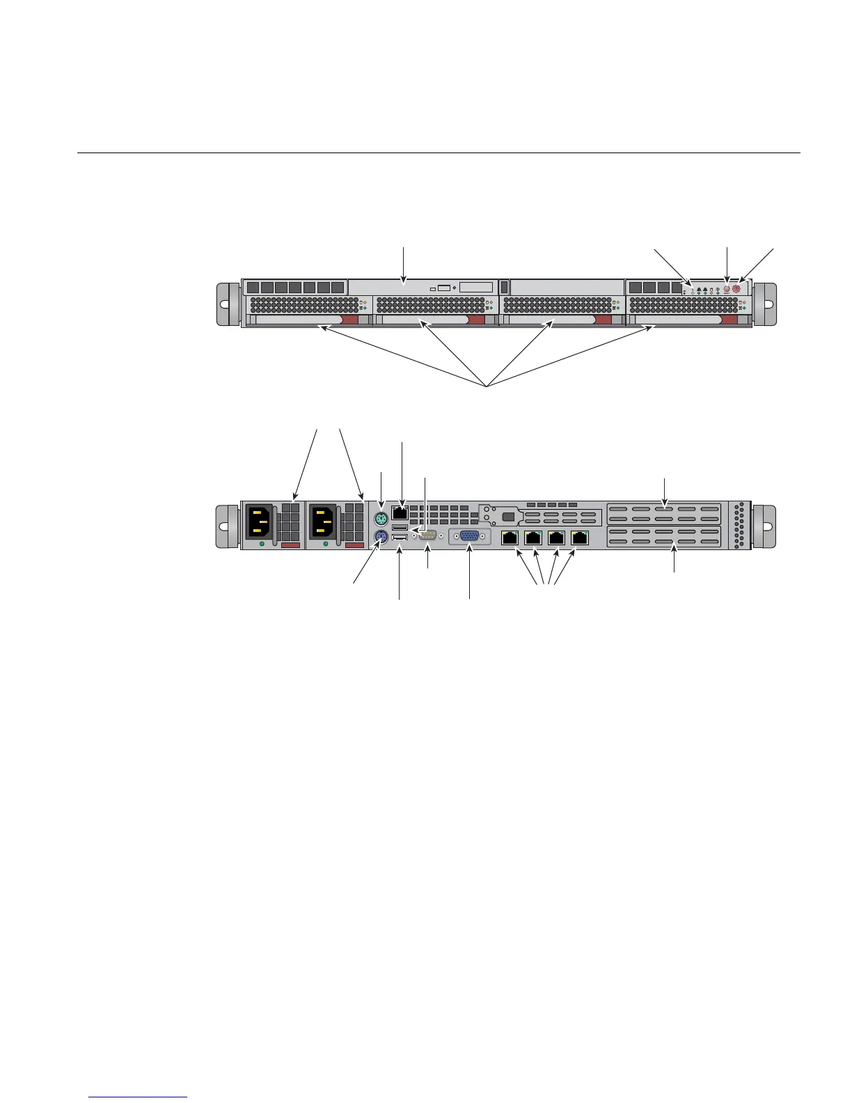
Figure 2-1 System Management Node Front and Rear Panels
CMC Overview
The CMC system for the SGI UV 2000 servers manages power control and sequencing, provides
environmental control and monitoring, initiates system resets, stores identification and
configuration information, and provides console/diagnostic and scan interface. A CMC port from
each chassis management controller connects to a dedicated Ethernet switch that provides a
synchronous clock signal to all the CMCs in an SSI.
Viewing the system from the rear, the CMC blade is on the right side of the IRU. The CMC
accepts direction from the SMN and supports powering-up and powering-down individual or
groups of compute blades and environmental monitoring of all units within the IRU. The CMC
sends operational requests to the Baseboard Management Controller (BMC) on each compute
Slim DVD drive option
System
reset
System
LEDs
Mai
pow
Disk drive bays
Mouse
BMC Port
USB
Port 1
Power Supply Module
USB
Port 0
Keyboard
VGA Port
COM
Port1
LAN ports 1-4
Full-height (full-depth)
x16 PCIe slot
Full-height (half-depth)
x16 PCIe slot