74 007-5832-002
7: Troubleshooting and Diagnostics
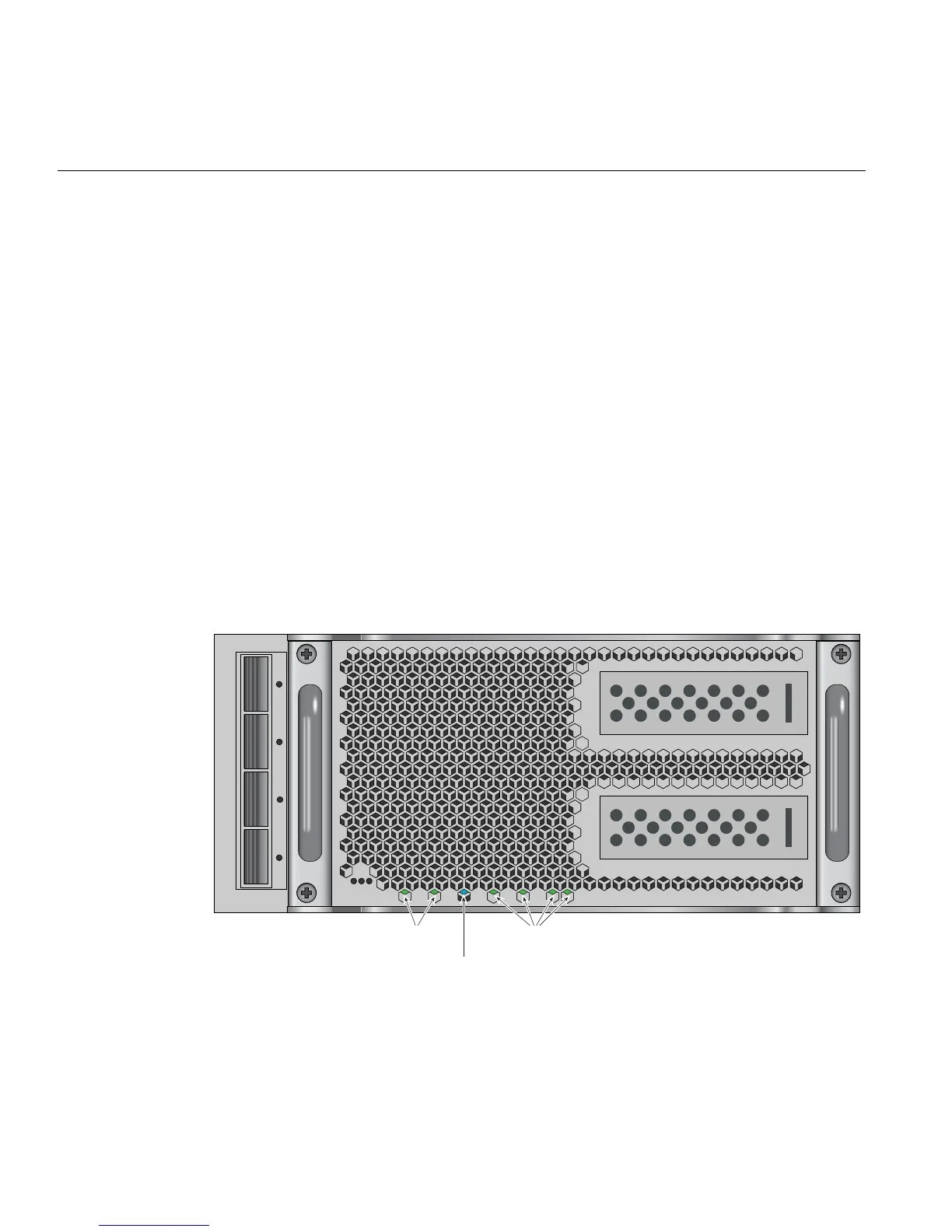
Compute/Memory Blade LEDs
Each compute/memory blade installed in an IRU has a total of seven LED indicators visable
behind the perforated sheetmetal of the blade.
At the bottom end (or left side) of the blade (from left to right):
• System power good green LED
• BMC heartbeat green LED
• Blue unit identifier (UID) LED
• BMC Ethernet 1 green LED
• BMC Ethernet 0 green LED
• Green 3.3V auxiliary power LED
• Green 12V power good LED
If the blade is properly seated and the system is powered on and there is no LED activity showing
on the blade, it must be replaced. Figure 7-1 shows the locations of the blade LEDs.
Figure 7-1 UV Compute Blade Status LED Locations Example
Blue LED
Green LEDsGreen LEDs