47
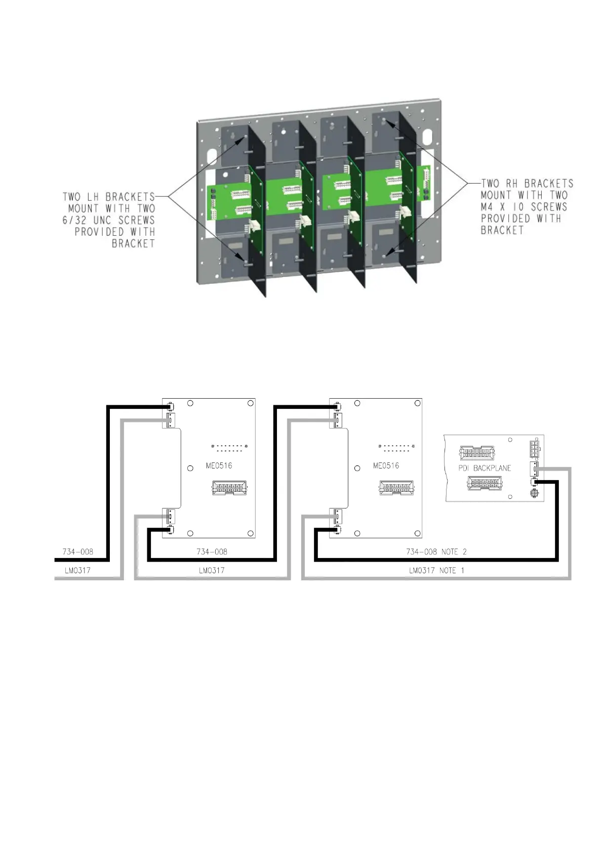
Figure 34. 8U Panel gear plate mounting
There are four possible mounting positions for the ME0516 in an 8U expansion cabinet. The recommended
mounting position for the 4100-6072/6073 SM Fibre Modem is at the left, see Figure 33.
Panel connection
Figure 35. Connection of Dual PDI Card Brackets to a panel backplane in 15U or 8U cabinets
1. A LM0317 Signal Power Loom is required to power 4100-6077AU MX Loop Cards. It is not
required for other cards. It is compatible with 15U and 8U cabinets. The PDI backplane in the
expansion bay of large rack cabinets is not compatible with the LM0317 Signal Power Loom.
2. A 734-008 Power/Comms loom connects to the ME0516 PCB for all PDI cards except the
4100-6072/6073 SM Fibre Modem. A 734-008 Power/Comms loom connects directly to
4100-6072/6073 SM Fibre Modems. A second 734-008 loom is required to link between
two SM modem cards. These cards must be at the end of a daisy chain connection because the
communications signals are not connected through the modem cards.