54
Adding a power supply
ME0504 APS
The APS occupies two PDI positions, one above the other, and supplies power directly to the PDI backplane for
use by other 4100ESi cards. Other system loads can be wired to the APS VAUX (1-3) outputs and the
NAC (1-3) outputs. Refer to LT0432 4100ESi Field Wiring Manual sheet 707 for wiring details.
The 734-301 signal power loom can be used to connect signal power from one PDI backplane to another. It
connects between a PDI socket, located behind the APS unit, to a PDI socket on the other PDI backplane.
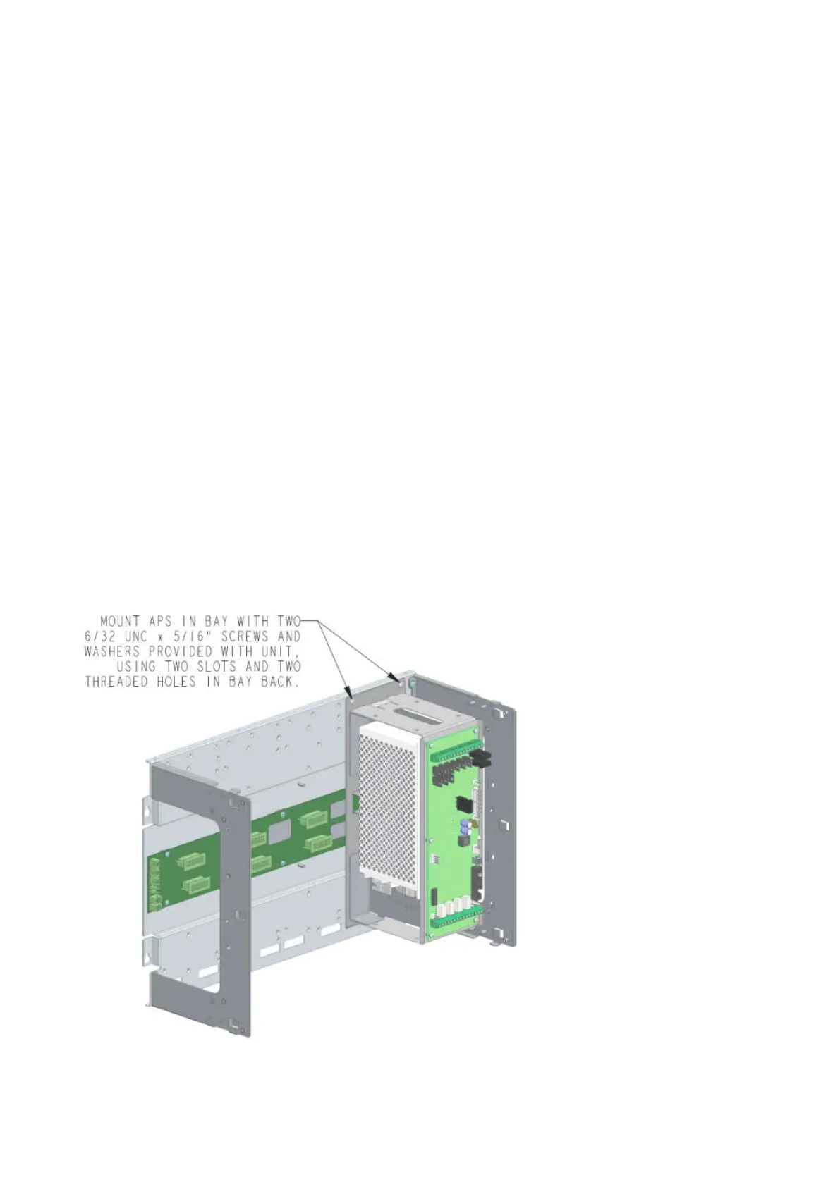
To install the ME0504 APS in a bay, complete the following steps:
1. Insert the tabs at the bottom of the power supply into the slots in the bay.
2. Pivot the ME0504 APS up to fit correctly onto the PDI connector underneath it.
3. Fasten the top of the power supply to the bay using the screws and washers included in the kit.
4. Set the address switch of the APS to match the configuration in the 4100ESi. For programming
information to configure the additional APS, see LT0619 4100ESi Programming Manual.
5. Plug the mains lead into the IEC socket on the bottom of the APS, and plug the 3 pin plug into the mains
outlet in the panel.
6. If necessary, fasten the mains lead to the outside end of the bay to secure any excess cable.
Figure 40. Mounting the APS in a bay