76
Appendix B Cable characteristics
MX Addressable Loop
MX cabling should be arranged in Class A loop style, but this loop can have Class B spur wiring
connected to it. To comply with AS 1670.1 requirements, each spur must not cover more than a
single detection zone, or have devices serving more than one function.
The MX loop wiring for each MX Loop Card should not exceed these limits:
⋅ Devices per loop: up to 250.
⋅ Wire size 0.8-3.3mm².
⋅ Wiring distance not more than 2000 meters around the loop.
⋅ Cable resistance not more than 150Ω, capacitance not more than 0.2µF, inductance not more
than 1.5mH.
⋅ Cable screen should be earthed only at the loop card.
MX Loop characteristics:
⋅ Maximum loop voltage: 40VDC.
⋅ Maximum loop current: 500mA peak.
⋅ Earth fault detection: 10kΩ.
⋅ All loop wiring is supervised.
⋅ All loop wiring is power limited.
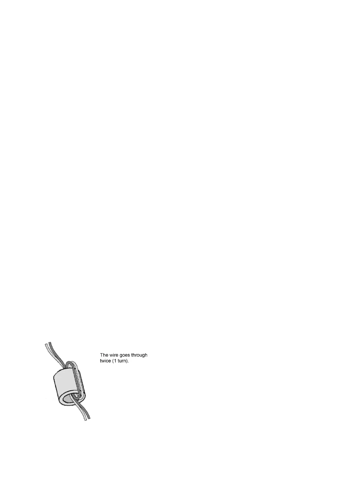
Use ferrite beads on each pair of wires leaving the 4100ESi cabinet, see Figure 58.
Figure 58. Ferrite bead wiring