Simrad AP21 and AP22 Autopilots
76 20220596G
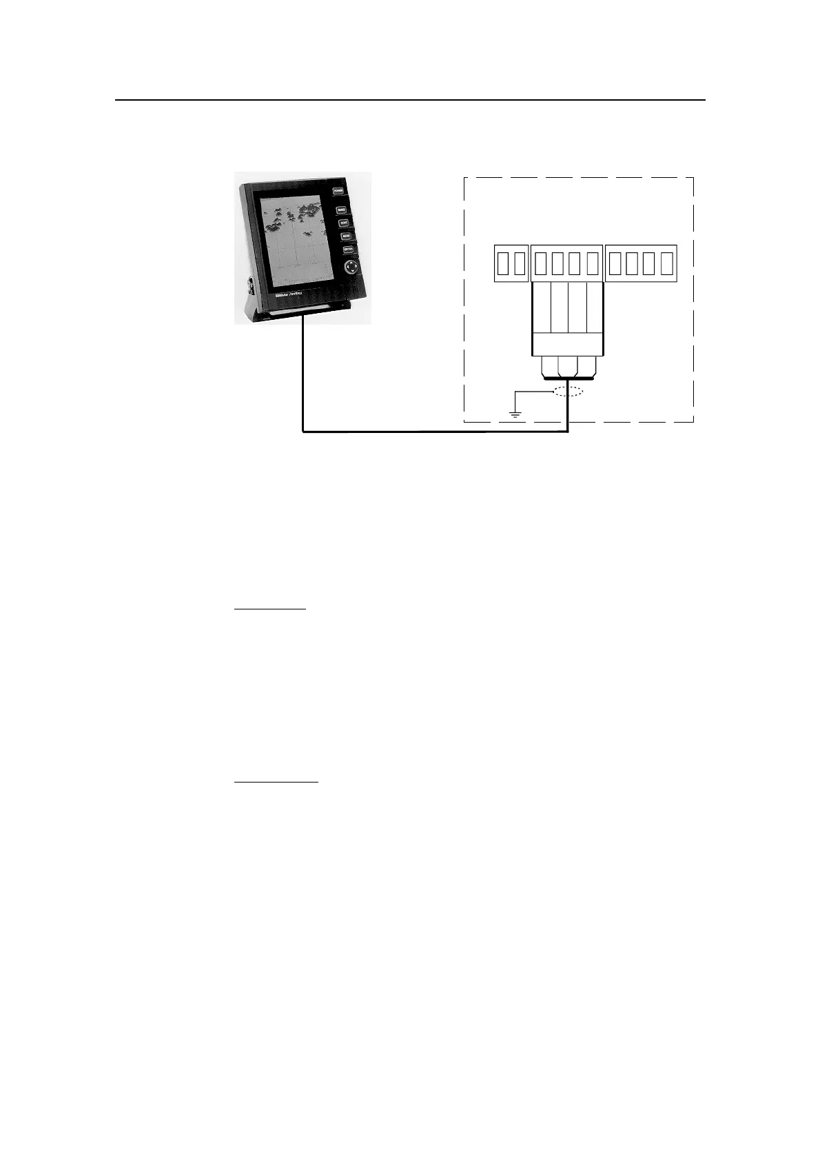
4.23 Radar Clock/Data
J300X JUNCTION UNIT
POWER PCB
Radar
TB8
TB9
TB10
Data_h
Data_c
Clk_h
Clk_c
ANRITSU
OR
FURUNO
RADAR
Figure 4-21 Radar Clock/Data connection
4.24 IS15 Instrument installation
For installation and operation of the IS15 instruments refer to
separate manuals.
NMEA In
This connection will provide speed, depth and temperature input
to the autopilot. If an IS15 Wind Transducer is connected to the
system, wind information will also be transferred to the autopilot.
The connection is made by a Roblink cable from the instrument
NMEA socket (4) to the J3xx Junction Unit Main Board,
Terminal RX1+ and RX1-. See Figure 4-22.
NMEA Out
This will provide the instrument system with heading data.
The connection is made by a Roblink cable from J3xx Junction
Unit Main Board, terminal TX1+ and TX1– to the instrument
NMEA socket (4). See Figure 4-22.
You will need a minimum of two instrument heads to make the
system both ‘listen’ and ‘talk’ (I/O).
If IS15 Expander is used in the instrument system, the NMEA
connections are made to this unit. See Figure 4-23.