Installation
20220596G 55
As many of the units are communicating on a common network
(ROBNET), with identical connectors, the installation is
simplified. Try to mount the units within the standard cable
length supplied with each unit, if possible. ROBNET Extension
Cable (10m) is available from your distributor.
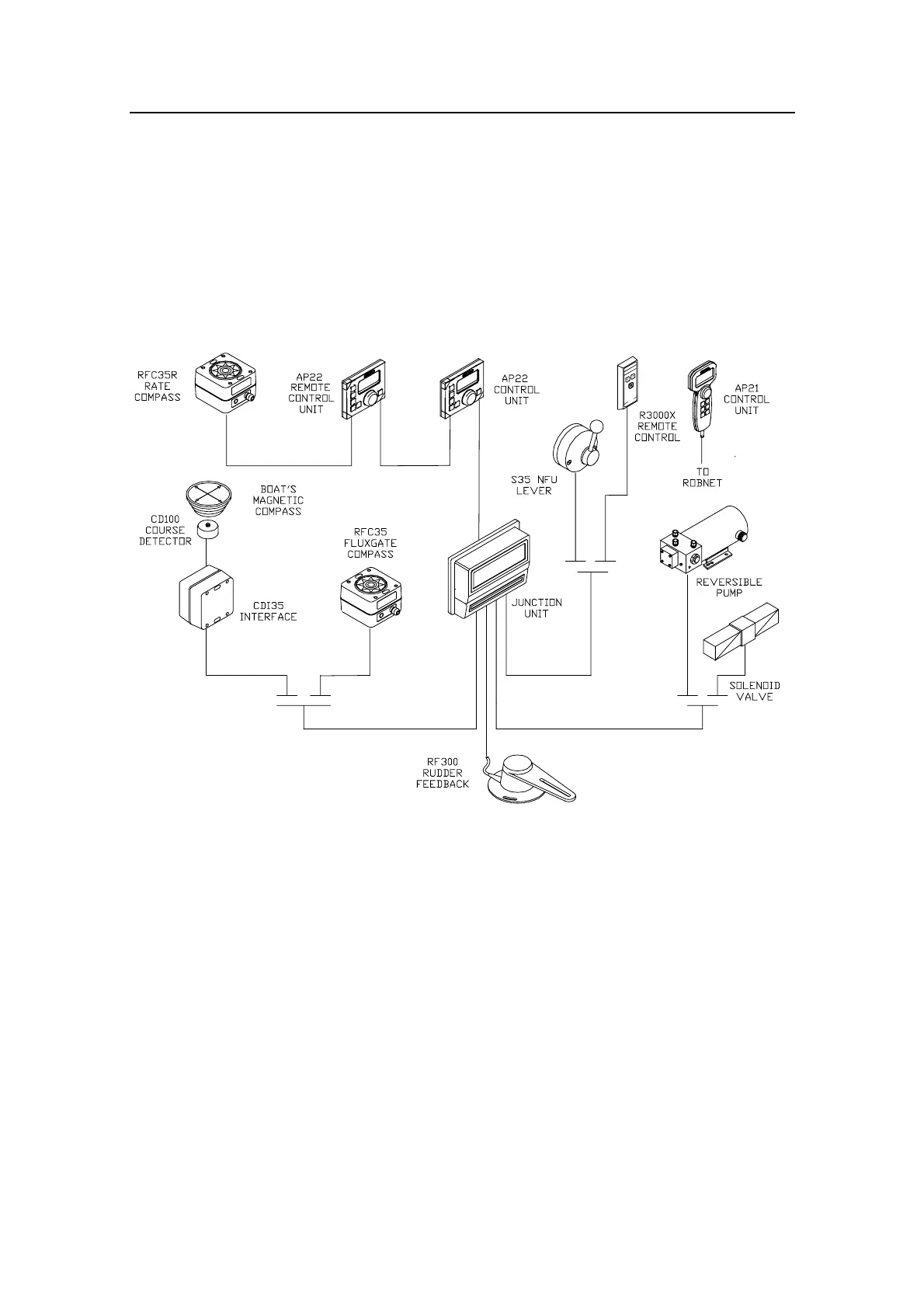
4.5 Autopilot System Layout
Figure 4-1 Autopilot system layout with options
4.6 RF300 Rudder feedback installation
The RF300 Rudder feedback unit mounts close to the rudder, and
is mechanically linked to the rudder tiller arm or rudder quadrant.
Refer to Figure 4-2 for the recommended mounting arrangement.
Note that the RF300 transmitter arm has two slots for the
transmission link. The slots enable maximum flexibility to
provide the 1:1 mechanical linkage relationship.
Note ! Do not try to remove the transmitter arm from the feedback unit.
The unit is factory adjusted and need no further adjustment at
installation than described below.