Simrad AP21 and AP22 Autopilots
56 20220596G
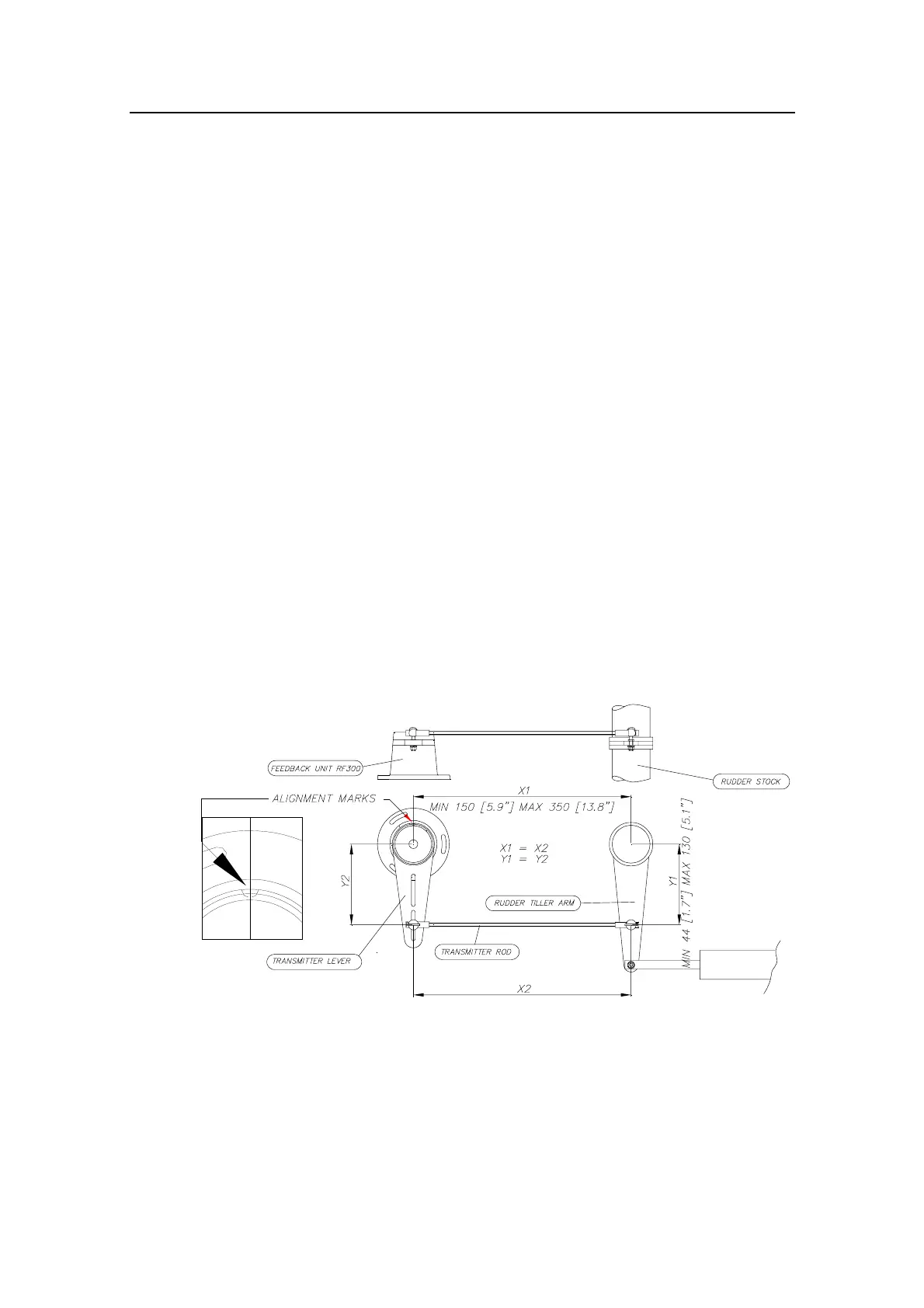
As a starting point, it is desirable to set the transmitter rod to the
inner limit of the outer slot if possible. (Refer to Figure 4-2).
Drill and tap the rudder tiller arm so that the Y1 dimension is
equal to the Y2 dimension (Use 4.2 mm drill and 5 mm tap).
Attach the ball joint to the tiller arm, and connect the transmitter
rod to the ball joint at the rudder tiller arm.
Turn the helm wheel to set the rudder tiller arm to approximate
centre position.
Rotate the RF300 transmitter lever until it is set to centre
position. (Use the alignment mark to line up the transmitter lever
to be opposite the cable entry into the feedback.).
Note ! Carefully observe the alignment marks. A rudder feedback alarm
may be the result if the alignment instructions as per Figure 4-2
are neglected.
Attach the transmitter rod to the RF300. Set the RF300 mounting
location to be in accordance with Figure 4-2. The centre of the
RF300 should be in line with the centre of the rudder post.
Mount the RF300 to a suitable platform using the screws
provided. If necessary, add blocking material under the RF300 to
adjust the height of the transmission arm to be level with the
rudder tiller arm.
Figure 4-2 RF300 mounting
Note ! Due to space limitations, it may be necessary to cut the length of
the transmitter rod to move the RF300 closer to the rudder post.
Tighten the mounting screws for both the RF300 feedback unit
and the transmitter rod ball joint.