Simrad AP21 and AP22 Autopilots
60 20220596G
4.10 Drive unit installation
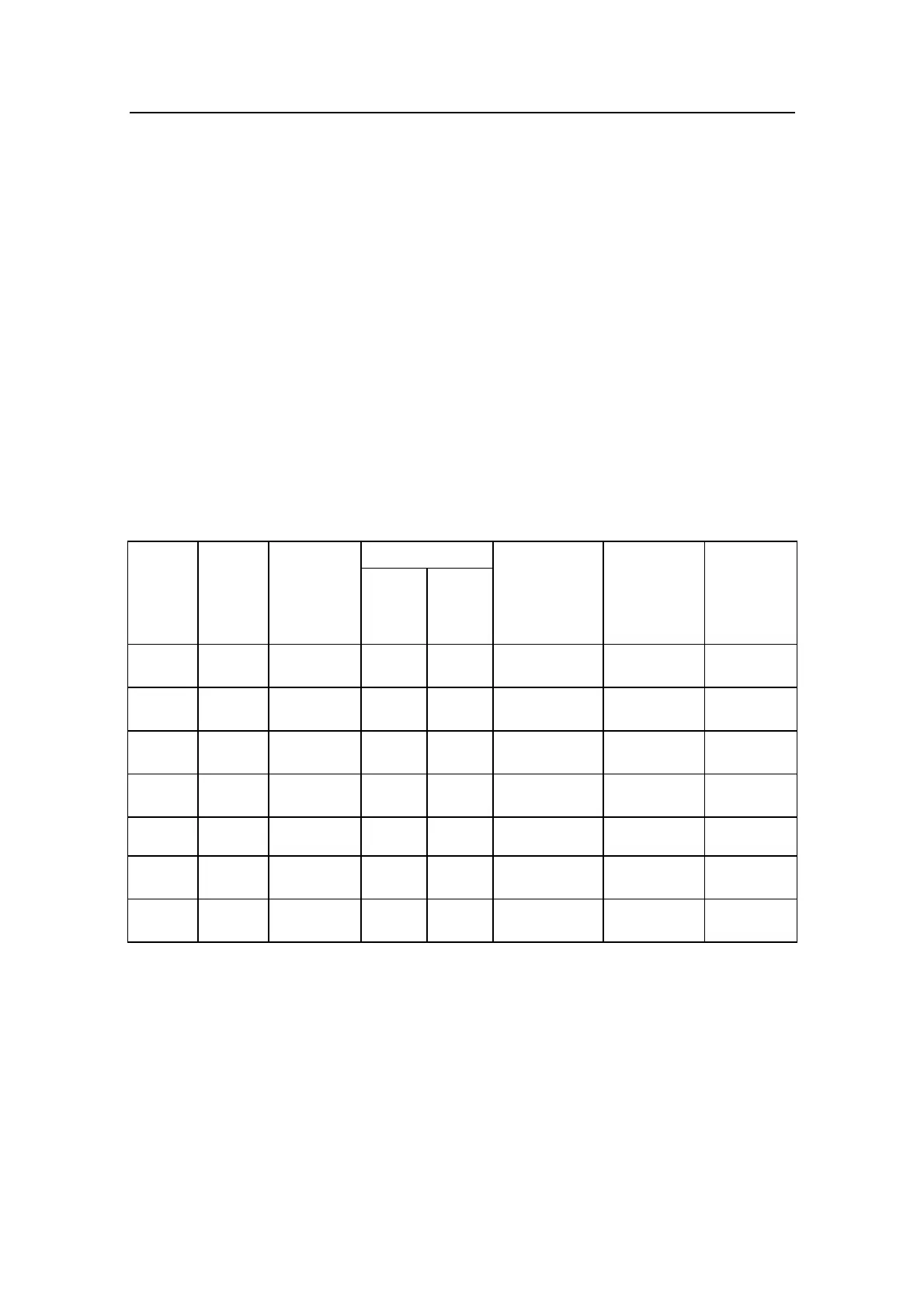
The relation between drive units, drive unit voltage, input
voltage, drive output and interfacing to steering gear are shown
in the table below. The autopilot system detects whether a
reversible motor or a solenoid is connected and outputs the
correct drive signal automatically.
Refer to the connecting diagram for the different drive units on
page 62 onwards.
Installation instruction for the drive units are found in the manual
for the individual units.
The maximum drive current capability of the J3000X, J300X and
J300X-40 junction units are different. Use the table below as
reference and observe the notes on next page.
HYDRAULIC PUMPS
RAM CAPACITY
MODEL MOTOR
VOLTS
JUNCTION
UNIT
MIN
cm
3
(cu. in.)
MAX
cm
3
(cu. in.)
FLOW RATE
AT 10 bar
cm
3
/min
(cu. in/min)
MAX
PRESSURE
bar
PWR.
CONSUM-
PTION
RPU80 12V J3000X 80 (4,9) 250
(15,2)
800 (49) 50 2,5-6 A
RPU160 12V J300X 160 (9,8) 550
(33,5)
1600 (98) 60 3-10 A
RPU200 24V J300X 190
(11,6)
670
(40,8)
2000 (122) 80 3-10 A
RPU300 12V J300X-40 290
(17,7)
960
(58,5)
3000 (183) 60 5-25 A
RPU300 24V J300X 290
(17,7)
960
(58,5)
3000 (183) 60 2,5-12 A
RPU3 24V J3000X 370
(22,4)
1700
(103)
3800/5000
(232/305)
40 7-22 A
RPU1 12V J3000X 140 (8,5) 600
(36,6)
1400/2000
(120/185)
40 7-22 A
Steering gear interface: Hydraulic plumbing