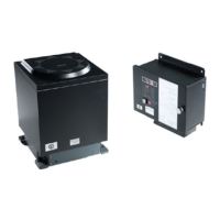
Simrad GC80/85 Compact MK2 Gyro Compass
51 988-12718-003
Note!
The foam rubber should be kept for re-use if the Master compass has to be
sent to factory for service!
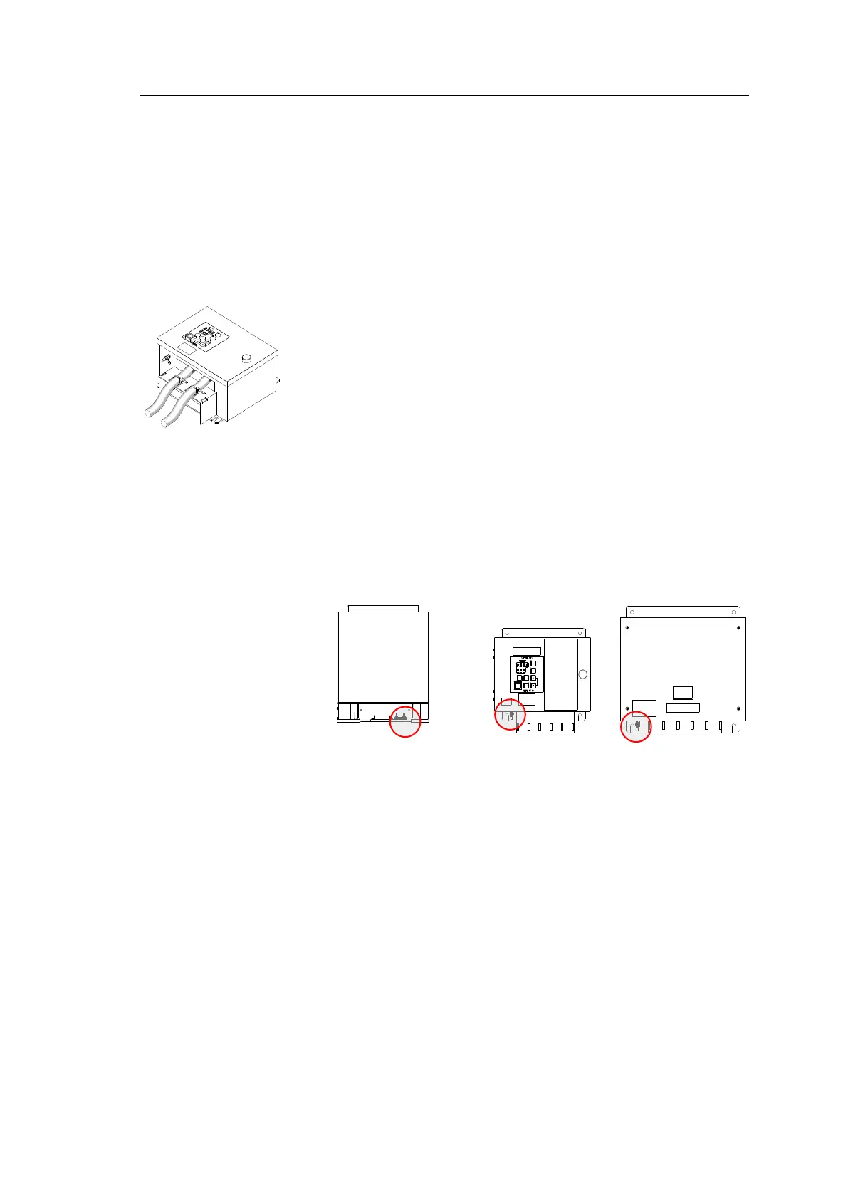
6.3 Cabling
Note!
No cables are included when the Gyro system is delivered from factory.
The wiring diagrams on page 84 onwards include cable specifications for
all cables.
Connect power and signal cables according to the wiring diagrams on
page 84 onwards.
To avoid cables to loosen due to vibration; the cables could be fastened to
the fixing device using wire straps as illustrated in the figure.
6.4 Grounding the units
All units in the GC80/85 system should have a proper ground connection
from the unit’s ground terminal.
The wires should be as short as possible and have a cross section of at least
AWG13 (2.5mm
2
).
MASTER COMPASS
COMPACT MK2
CONTROL UNIT
POWER SUPPLY
UNIT (OPTION)
6.5 DIP switch and jumper settings
GC80 and GC85 Gyro systems include several DIP switches and jumpers.
With the exception of 2 switches on the ICNT board in the Control unit, no
switches have to be set when installing the system. These 2 switches are
set to configure the Control unit to match the type of Gyro system (GC80
or GC85), and to activate an external heading sensor.
Note!
All DIP switch settings are read when the system is started. Any changes
made while the system is running will therefore not take effect until the
system is restarted.
For a complete list of DIP switch settings, refer to
DIP SWITCH SETTINGS
,
page 101.