Simrad GC80/85 Compact MK2 Gyro Compass
988-12718-003 16
3 USER INTERFACE
This section gives an overview of the GC80 Compact MK2 Control unit and
the user interface.
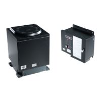
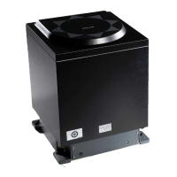
3.1 GC80 Compact MK2 Control unit
The Control unit includes the Control panel for the Gyro compass.
A flush mount kit (part number 27101757) may be ordered from Simrad for
remote installation of the Control panel. Refer
Flush mounting the
Control panel
, page 47.
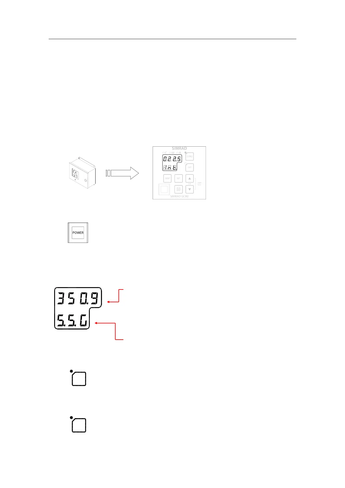
POWER button
Used for turning the Gyro system ON. The button will be lit to indicate that
power is supplied to the system. Refer
System start-up and
shut-down, page 19.
Display
The LCD displays data in 2 rows: the upper row shows data and the lower
row shows active mode.
- The Data indicator consists of 4 7-segments red LEDs.
The indicator is used to display the vessel’s bearing,
latitude and speed. Refer
Displaying present settings
page 22.
The Data indicator is also used for displaying alarm
codes as described from page 29
onwards.
- The Mode indicator consists of 3 7-segments green
LEDs. The Mode indicator displays codes used for
identifying input type for bearing, latitude and speed.
GYRO button
Used to select the Gyro compass as the active heading reference source.
The status lamp is lit to indicate that the Gyro system is active.
Refer
page 21.
EXT button
Used to select the external heading source as the heading reference. The
status lamp will be lit to indicate that the external heading reference source