Wiring
Access to connectors
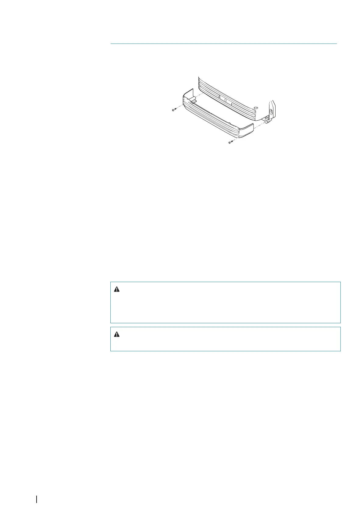
For easier access to connectors, remove the bottom front of the unit.
Wiring guidelines
Don't:
• Make sharp bends in the cables.
• Run cables in a way that allows water to flow down into the connectors.
• Run the data cables adjacent to radar, transmitter, or large/high current carrying cables or
high frequency signal cables.
• Run cables so they interfere with mechanical systems.
• Run cables over sharp edges or burrs.
Do:
• Make drip and service loops.
• Use cable-ties on all cables to keep them secure.
• Solder/crimp and insulate all wiring connections if extending or shortening the cables.
Extending cables should be done with suitable crimp connectors or solder and heat
shrink. Keep joins as high as possible to minimize possibility of water immersion.
• Leave room adjacent to connectors to ease plugging and unplugging of cables.
Warning: Before starting the installation, be sure to turn electrical power
off. If power is left on or turned on during the installation, fire, electrical
shock, or other serious injury may occur. Be sure that the voltage of the
power supply is compatible with the unit.
Warning: The positive supply wire (red) should always be connected to
(+) DC with a fuse or a circuit breaker (closest available to fuse rating).
Control devices
The system can be operated by:
• A supported remote controller connected via NMEA 2000.
• Touch monitors connected via serial interface (RS422) or USB.
• Keyboard and mouse/trackball connected via USB.
For wiring details, refer to the port description in the next pages.
Monitors
Up to two monitors may be connected via the HDMI ports.
Monitors with DVI inputs only should use an HDMI-DVI adaptor.
Ú
Note: Brightness control are not supported over DVI.
Monitors must conform to the supported resolutions and refresh rates as defined in the
Technical specification.
3
12
Wiring | NSO evo3S MPU Installation Manual