other directions. This energy is referred to as sidelobe energy and occurs in all radar systems.
The returns caused by sidelobes tend to appear as arcs.
Ú
Note: This control should only be adjusted by experienced radar users. Target loss in
harbor environments may occur if this control is not adjusted correctly.
When the radar is mounted where there are metallic objects near the radar, sidelobe energy
increases because the beam focus is degraded. The increased sidelobe returns can be
eliminated using the sidelobe suppression control.
By default, this control is set to auto and normally should not need to be adjusted. However,
if there is significant metallic clutter around the radar, sidelobe suppression may need to be
increased.
To adjust the sidelobe suppression value:
1. Set radar range to between 1/2 nm to 1 nm and the sidelobe suppression to auto
2. Take the vessel to a location where sidelobe returns are likely to be seen. Typically, this
would be near a large ship, container port, or metal bridge.
3. Traverse the area until the strongest sidelobe returns are seen.
4. Change auto sidelobe suppression to OFF, then adjust the sidelobe suppression control
just enough to eliminate the sidelobe returns. You may need to monitor 5-10 radar
sweeps to be sure they have been eliminated.
5. Traverse the area again and readjust if sidelobes returns still occur.
Sector blanking
Radar installed in close proximity to a mast or structure could cause unwanted reflections or
interference to appear on the radar image. Use the sector blanking feature to stop the radar
from transmitting on up to four sectors in the image.
Ú
Note: Sectors are setup relative to the heading line of the radar. The bearing of the
sector is measured from the center line of the sector.
Ú
Note: Sector blanking should be applied very carefully to avoid reducing the radar’s
usefulness in identifying valid and potentially dangerous targets.
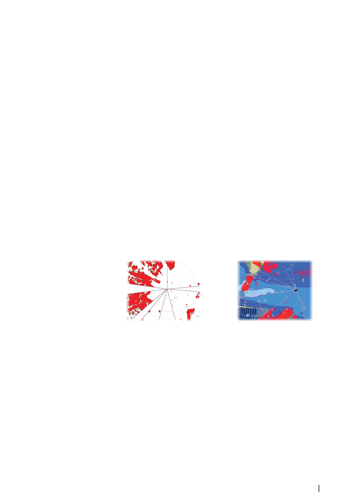
Main radar PPI Radar overlay on a chart
Adjust open array park angle
The park angle is the final resting position of the antenna relative to the heading line of the
radar when the radar is set to standby. The antenna will stop rotating at the desired offset.
Adjust local interference reject
Interference from some onboard sources can interfere with the Broadband radar. One
symptom of this could be a large target on the screen that remains in the same relative
bearing even if the vessel changes direction.
Halo light
Controls the levels of the Halo Radar blue accent lighting. The accent lighting can only be
adjusted when the radar is in standby mode.
Ú
Note: The blue accent pedestal lighting might not be approved for use in your boating
location. Check your local boating regulations before turning the blue accent lights ON.
System setup | NSO evo3S MPU Installation Manual
25