Power
The power connector is used for power, power control and for external alarm output.
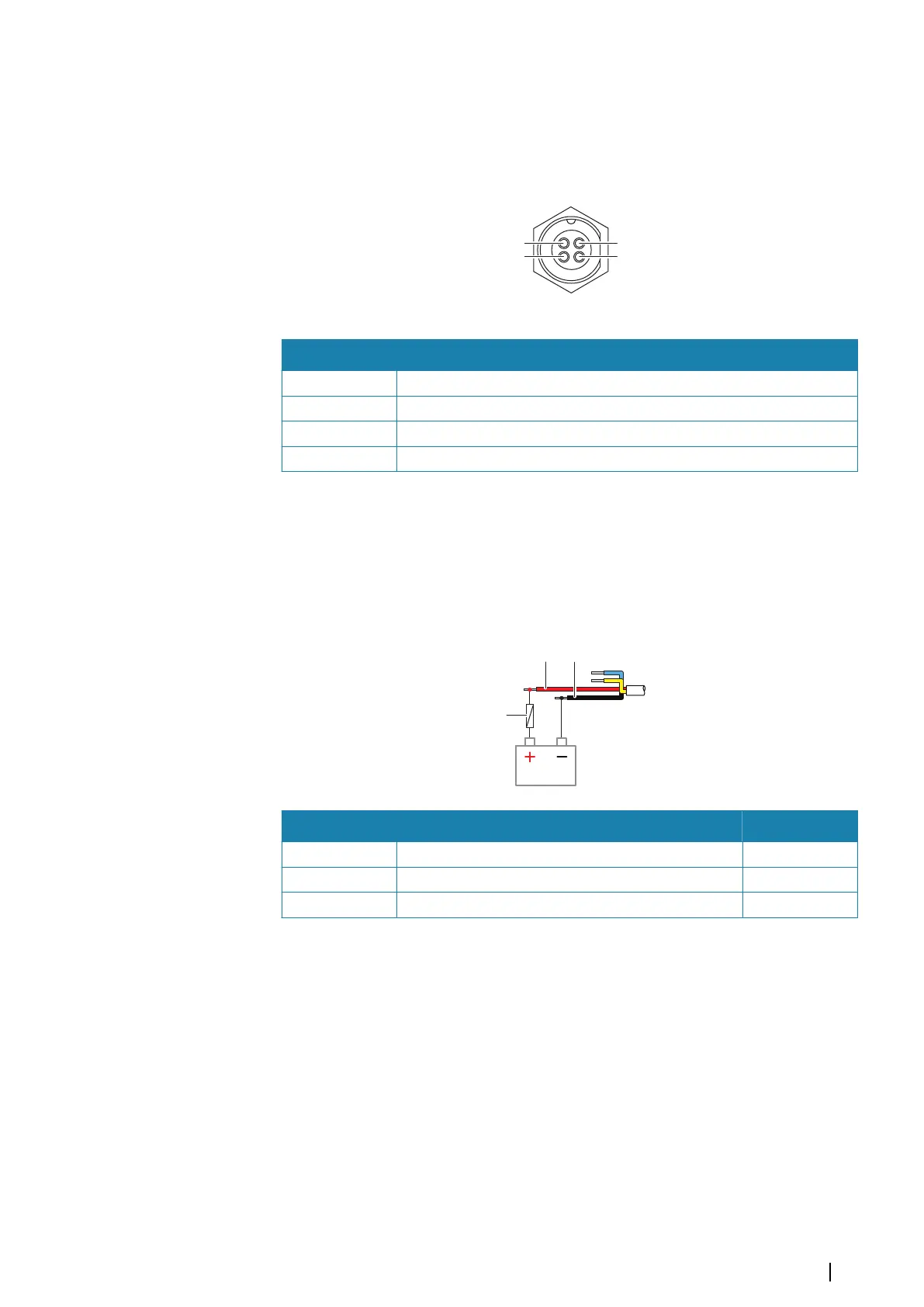
Power connector details
Unit socket (male)
Pin Purpose
1 DC negative
2 External alarm
3 Power control
4 +12/24 V DC
Power connection
The unit is designed to be powered by 12 or 24 V DC system.
It is protected against reverse polarity, under voltage, and over voltage (for a limited
duration).
A fuse or circuit breaker should be fitted to the positive supply. For recommended fuse rating
refer to "Technical specifications" on page 39.
Key Purpose Color
A +12/24 V DC Red
B DC negative Black
C Fuse
Power control connection
The yellow wire in the power cable can be used to control how the unit is turned on and off.
Power controlled by power key
The unit will turn on/off when the power key on the unit is pressed.
Leave the yellow power control wire disconnected and tape or heat-shrink the end to
prevent shorting.
Power control by supply power
The unit will turn on/off without using the power key when power is applied/removed.
Connect the yellow wire to the red wire after the fuse.
Ú
Note: The unit cannot be powered down by power button, but can be put in to standby
mode (the screen backlight turns off).
Wiring | NSO evo3S MPU Installation Manual
13