BOOM AND PLATFORM ASSEMBLY
AB16EJ Plus Maintenance Manual 53
© Mar. 2023
Disassembly
• Before disassembling the articulated boom
assembly, rotate the boom tube to be parallel
to the travel direction of the chassis, and make
sure the turntable is locked (if equipped with a
rotary pin, make sure the rotary pin is locked).
• Before disassembling the articulated boom
assembly, place solid and reliable rigid brack-
ets under the counterweight for support, or the
machine may tip over, causing serious person-
al injury and machine damage.
1. Raise the boom tube slightly until the articulated
boom assembly can be easily removed.
2. Remove the main boom assembly, main boom lift
cylinder, and downward leveling cylinder.
3. Mark and disconnect all harness connections on the
articulated boom assembly.
4. Mark and disconnect all hydraulic pipelines on the
articulated boom assembly and collect the hydraulic
oil in the pipelines with a suitable vessel. Then seal
the pipelines and ports.
5. Reliably support the upper and lower connectors
with suitable lifting equipment.
6. Reliably support the lower linkage and upper articu-
lated boom with suitable lifting equipment.
7. Remove the bolt and nut at the pivot pin #3 connect-
ing the lower linkage with the lower connector, and
knock out the pivot pin #3 with a brass rod and
mallet.
8. Remove the bolt and nut at the pivot pin #8 connect-
ing the lower linkage with the turntable, and knock
out the pivot pin #8 with a brass rod and mallet.
9. Slowly remove the lower linkage with the aid of the
lifting equipment.
10. Remove the bolt and nut at the pivot pin #4 connect-
ing the upper articulated boom with the pull rod, and
knock out the pivot pin #4 with a brass rod and
mallet.
11. Remove the bolt at the pivot pin #1 connecting the
upper articulated boom with the upper connector,
and knock out the pivot pin #1 with a brass rod and
mallet.
12. Slowly remove the upper articulated boom with the
aid of the lifting equipment.
13. Remove the articulated boom lift cylinder.
14. Reliably support the upper linkage with suitable lift-
ing equipment.
15. Remove the bolt at the pivot pin #2 connecting the
upper linkage with the upper connector, and knock
out the pivot pin #2 with a brass rod and mallet.
16. Slowly remove the upper connector with the aid of
the lifting equipment.
17. Remove the bolt and nut at the pivot pin #5 connect-
ing the upper linkage with the lower connector, and
knock out the pivot pin #5 with a brass rod and
mallet.
18. Slowly remove the upper linkage with the aid of the
lifting equipment.
19. Reliably support the lower articulated boom with
suitable lifting equipment.
20. Remove the bolt and nut at the pivot pin #6 connect-
ing the lower articulated boom with the lower con-
nector, and knock out the pivot pin #6 with a brass
rod and mallet.
21. Slowly remove the lower connector with the aid of
the lifting equipment.
22. Remove the bolt and nut at the pivot pin #9 connect-
ing the lower articulated boom with the turntable,
and knock out the pivot pin #9 with a brass rod and
mallet.
23. Slowly remove the articulated boom with the aid of
the lifting equipment.
Installation
Follow the reverse order of the disassembly procedures.
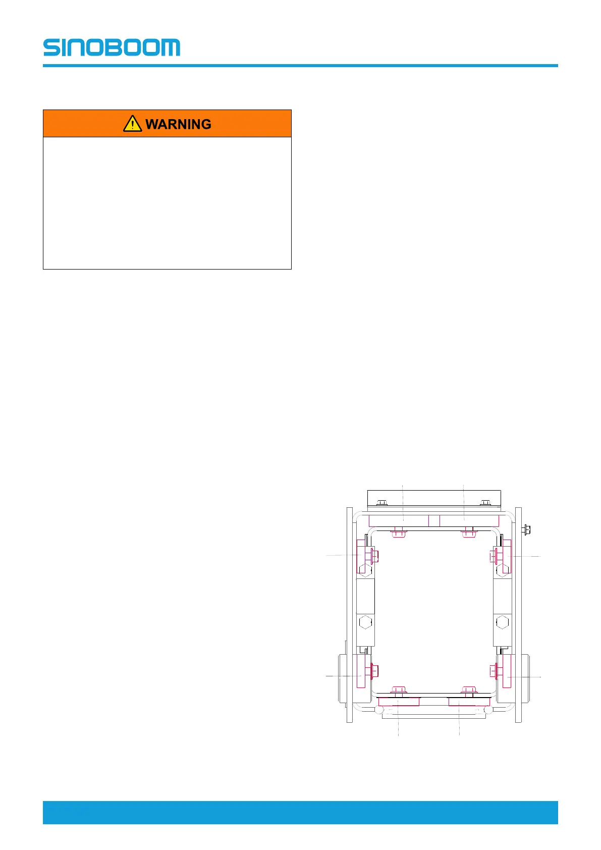
Boom Slider
Fig 8 Diagram of sliders at boom head