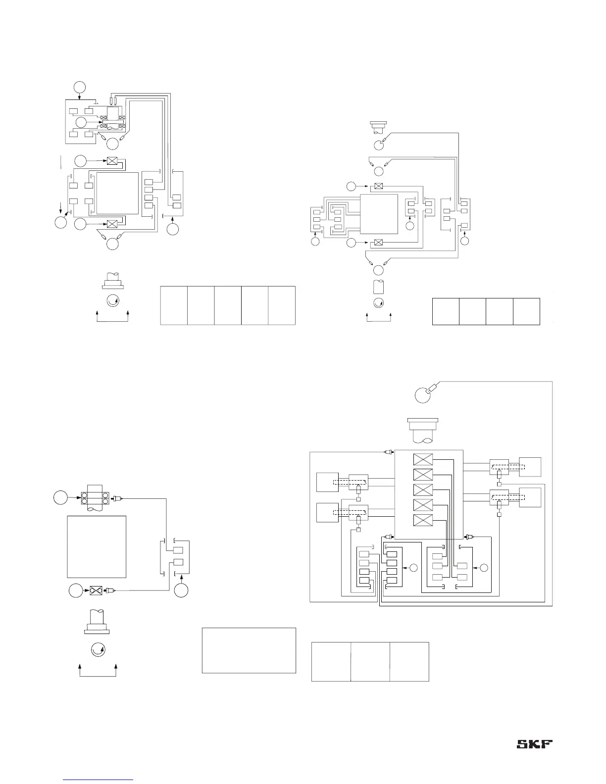
Figure 2-3. Typical system arrangement for a centrifugal compressor
or a pump with hydrodynamic bearings.
Vibration, Axial Position and T e mperature Monitor
P1
P1
P1
P2
P2
P2
3Y
3Y
4X
4X
5Y
5Y
5Y
6X
6X
6X
T2
T5 T6
T8
T7
T4
JB
JB
JB
4X
3Y
R
R
T3
T1
T5, T6,
T7 ,T8
Active thrust
T
Radial
vibration
inboard
Counter-
clockwise
rotation
viewed here
Axial
position
Radial
bearing
temperature
NOTES:
1. TDC – top dead center.
Radial
vibration
outboard
Thrust
bearing
temperature
Description
Axial position probe (instrument manufacturer
ID data)
Axial position probe (instrument manufacturer
ID data)
Inboard end radial vibration probe, 45° left of
TDC (instrument manufacturer ID data)
Inboard end radial vibration probe, 45° right
of TDC (instrument manufacturer ID data)
Outboard end radial vibration probe, 45° left
of TDC (instrument manufacturer ID data)
Outboard end radial vibration probe, 45° right
of TDC (instrument manufacturer ID data)
Radial bearing (description)
Thrust bearing (description)
Junction box (description)
Outboard end bearing temperature
Coupling end bearing temperature
Active thrust bearing temperature
Inactive thrust bearing temperature
Item
P1
P2
3Y
4X
5Y
6X
R
T
JB
T1, T2
T3, T4
T5, T6
T7, T8
Centrifugal
compressor or
pump
T1, T2,
T3, T4
Figure 2-4. Typical system arrangement for an electric motor with
sleeve bearings.
T4
T4
T9
T2
T2
4X
4X
T8T6
R
R
6X
6X
3Y
3Y
5Y
5Y
JB
JB
JB
T10
Ø
Ø
T7T5
T3
T3
T1
T1
Motor
Counter-
clockwise
rotation
viewed here
NOTES:
1. TDC – top dead center.
Description
Outboard end Y radial vibration
probe, 45° left of TDC
(instrument manufacturer ID data)
Outboard end X radial vibration
probe, 45° right of TDC
(instrument manufacturer ID data)
Inboard end Y radial vibration
probe, 45° left of TDC
(instrument manufacturer ID data)
Inboard end X radial vibration
probe, 45° right of TDC
(instrument manufacturer ID data)
Phase reference probe, 45° right
of TDC (instrument manufacturer
ID data)
Outboard end bearing temperature
Inboard end bearing temperature
Radial bearing (description)
Junction box (description)
Motor winding temperature
(phase A)
Motor winding temperature
(phase B)
Motor winding temperature
(phase C)
Item
5Y
6X
3Y
4X
Ø
T1, T2
T3, T4
R
JB
T5, T6
T7, T8
T9, T10
Vibration and Temperature Monitor
5Y
3Y
Radial shaft
vibration
coupling
end
Motor
winding
temperature
Radial shaft
vibration
outboard
Bearing
temperature
T1, T2, T3, T4
T5, T6, T7,
T8, T9, T10
6X 4X
Figure 2-5. Typical system arrangement for a Pump or Motor with
rolling element bearings.
Vibration Monitor
A1
JB
A2
A2
A1
R
T/R
Pump
Bearing cap vibration
Counter-
clockwise
rotation
viewed here
NOTES:
1. TDC – top dead center.
2. The same arrangement would be
used for a motor with rolling
element bearings but would be
viewed from the outboard end.
Description
Inboard end radial horizontal
accelerometer, 90° off TDC
(instrument manufacturer ID data)
Outboard end radial horizontal
accelerometer, 90° off TDC
(instrument manufacturer ID data)
Radial bearing (description)
Thrust/Radial bearing (description)
Junction box (description)
Item
A1
A2
R
T/R
JB
Inboard end
A1
Outboard end
A2
Section 2 – Typical eddy probe arrangement plans
2-2
Typical eddy probe arrangement plans
Figure 2-6. Typical system arrangement for a reciprocating
compressor.
Rod Drop, Vibration and Bearing
Temperature Monitor System
T1
T1
T2
T2
T3
T3
T4
T4
T5
T5
A2
A2
Ø1
Ø1
A1
A1
A3
A3
JB
JB
RD1
RD1
RD2
RD2
RD3
RD3
RD4
RD4
Reciprocating
Compressor
Cylinder
3
A1, A2, A3
Piston
Rod Drop
Channels
Casing
Vibration
Channels
Bearing
Temperature
Channels
T1, T2, T3. T4, T5
RD1, RD2, RD3, RD4
Cylinder
1
Cylinder
4
Cylinder
2
Description
Phase reference transducer
Radial bearing (description)
Junction box (description)
Main bearing temperatures
Rod drop probes (instrument
manufacturer ID data)
Casing Accelerometers
Item
Ø1
R
JB
T1-T5
RD1-RD4
A1, A2,A3