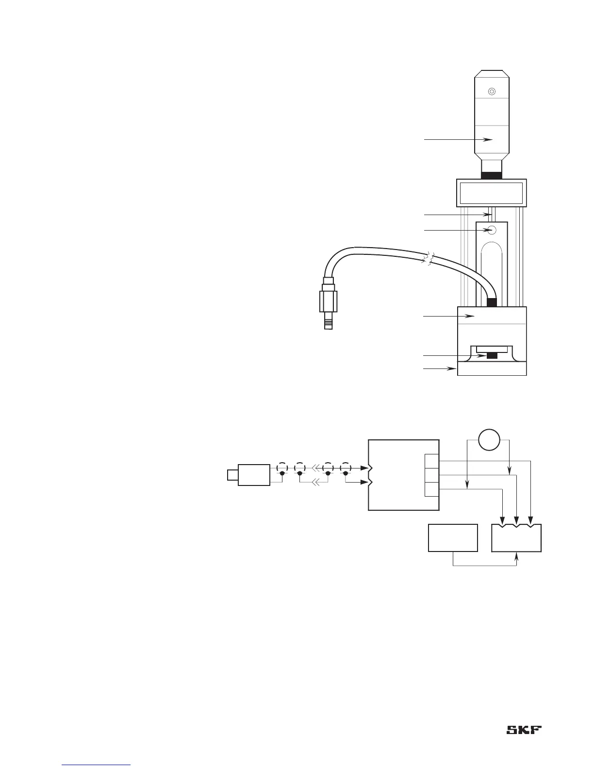
Set-up procedure (Figure 6-1)
Insert the adapter through the hole in the magnetic 1.
base B.
Slip the probe into the adapter and lock into place with 2.
the set screw A. Be sure that the entire non-metallic
portion of the probe tip extends beyond the end of the
adapter.
Slip the adapter over the end of the micrometer head C. 3.
Lock it into place with set screw D.
Attach magnetic base to the machine shaft or to the 4.
target plate E supplied with the kit or a target provided
by the user.
Connect the probe lead to the appropriate CMSS 900 or 5.
CMSS 958 Extension Cable and connect the extension
cable to the appropriate probe driver (CMSS 600 Driver
for CMSS 60 Series Probes, CMSS 606 Driver for CMSS
61 Series Probes, CMSS 665 Driver for CMSS 65 Series
Probes, CMSS 668 Driver for CMSS 68 Series Probes).
Apply -24 Vdc power to the driver, and connect a 6.
voltmeter to the driver output (Figure 6-2).
Rotate spindle scale F to read “40 mils” (1 mm). Loosen 7.
set screw D, and move Probe to read -8 Vdc on the
voltmeter (without disturbing reading; spindle continues
to read “40 mils” [1 mm] ). Lock set screw D, and
proceed with calibration.
Proceed with calibration procedure 8.
on page 6-4.