The drivers can be mounted inside the housing on ordinary
steel “Type C DIN-rails” which is available from almost any
electrical supply outlet.
Figure 4-15 shows how to install the drivers using the
DIN-rail and clip.
Figure 4-15. Installation of srivers in recommended explosion-proof
housings.
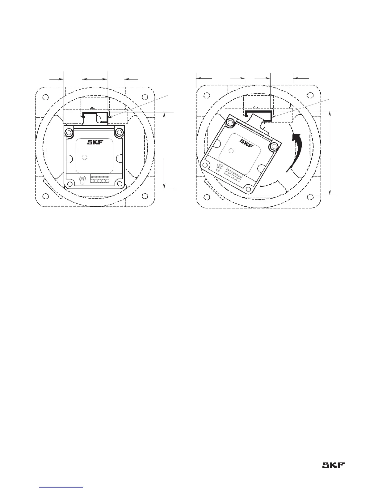
Figure 4-16 shows the minimum clearances needed to
install the drivers in explosion-proof housings. These
clearances allow for the cables and for the “swing” involved
in snapping the driver clip into the DIN-rail.
Figure 4-16. Minimum clearances needed to install drivers in
explosion-proof housings.