Section 4 – Driver installation
4-1
Section 4
Driver installation
Introduction
This section explains how to install SKF Eddy Probe Drivers
(electrical and mechanical). Figure 4-1 shows typical
drivers.
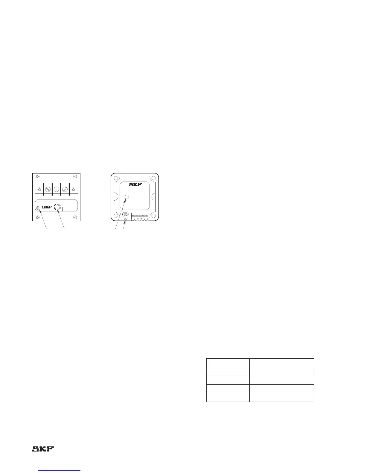
Figure 4-1. Typical SKF Eddy Probe Driver.
CAL adjustment (R1)
Adjusts sensitivity of probe and driver (slope of volts/mil
calibration curve). Adjustment voids factory calibration.
Used for adjustment to alternate target materials.
PROBE connector (J1)
Subminiature coaxial connector. Mates with connector
on CMSS 900 or CMSS 958 Extension Cable. In unique
special probe application where extension cable is integral
to the probe, then this connector can mate with connector
on the probe.
Terminal strip connectors
-24 Vdc accepts power for electronic circuits.•
COM is the common connection for -24 Vdc and •
OUTPUT terminals.
OUTPUT• provides voltage-proportional-to-gap output for
monitor system or readout instrument.
The driver must be mounted where it can be connected to
the probe via the extension cable (probe to driver = 5
meters). Because the eddy probe is a “tuned” circuit, the
extension cable must be used; it must not be eliminated
from the installation, shortened, or extended.
SKF Eddy Probe Drivers have a power supply rejection ratio
of approximately 100 to 1 (a 1-volt drift in power supply
voltage will cause no more than a 0.01 volt change in the
driver OUTPUT signal). Exception – CMSS 600, CMSS
606, and CMSS 620-2.
Note: Refer to Table 1-1 for probe/driver compatibility.
Electrical
Power/signal cable should be a shielded 3-wire cable.
The shield helps prevent “electrical noise” found in most
operating environments from affecting the probe’s signal.
The shield should be grounded at one place only (floating
or differential).
The shield can be grounded to any of the following points
(do not ground at both ends to prevent ground loops).
•Monitorchassisgroundscrew
•Monitorcircuitground“COM”terminal
•Driverchassis(Machineryground)
•Facilityinstrumentation“Earth”ground
The cable’s wire size (AWG) affects the usable distance from
the driver and the monitor equipment. See Table 4-1.
Table 4-1. Driver to monitor maximum wire lengths.
Wire size (AWG) Distance (Maximum)
22 1,000 feet (303 meters)
20 2,000 feet (606 meters)
18 3,000 feet (909 meters)
13 4,000 feet (1,212 meters)