JB
S
Ø
S9
Ø10
Ø10
3Y
4X
4X
P2
P2
P2
JB
P1
P1
P1
4X
3Y
3Y
T
R
R
6X
6X
6X
5Y
5Y
5Y
S8
S7
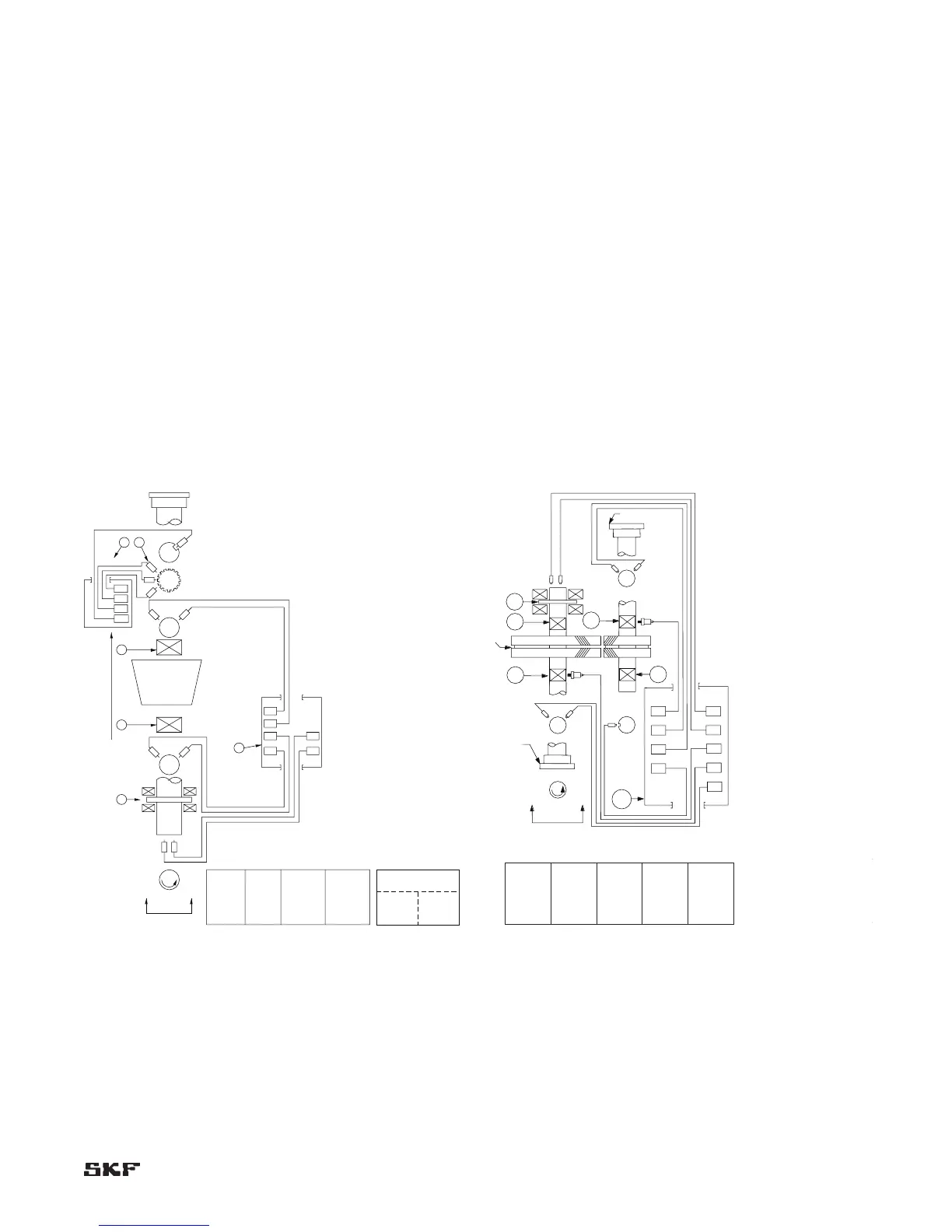
Vibration, Axial Position, Speed
and Temperature Monitor
Tachometer
Radial shaft
vibration
high pressure
Redundant
Power
Supplies
3 Overspeed
Sensing
Channels
S7 S8 S9
Counter-
clockwise
rotation
viewed here
Turbine
Active Thrust
Axial
Position
Radial shaft
vibration
low pressure
Overspeed Detection
System
NOTES:
1. TDC – top dead center.
2. Typical temperature sensors and
monitors are shown in Figure 2-3.
Description
Axial position probe (instrument
manufacturer ID data)
Axial position probe (instrument
manufacturer ID data)
Low pressure end radial vibration
probe, 45° left of TDC (instrument
manufacturer ID data)
Low pressure end radial vibration
probe, 45° right of TDC (instrument
manufacturer ID data)
Low pressure end radial vibration
probe, 45° left of TDC (instrument
manufacturer ID data)
Low pressure end radial vibration
probe, 45° right of TDC (instrument
manufacturer ID data)
Phase reference transducer, 45°
right of TDC (instrument
manufacturer ID data)
Radial bearing (description)
Thrust bearing (description)
Junction box
Overspeed sensors
Item
P1
P2
3Y
4X
5Y
6X
Ø
R
T
JB
S7-S9
3Y
3Y
4X
4X
A1
A1
P1
P1
P2
P2
5Y
5Y
A2
A2
6X
6X
JB
T
R
R
R
R
Ø1
Ø1
Input shaft
Gear
Output shaft
Counter-
clockwise
rotation
viewed here
Description
Input shaft coupling end Y radial
vibration probe, 45° left of TDC
(instrument manufacturer ID data)
Input shaft coupling end X radial
vibration probe, 45° right of TDC
(instrument manufacturer ID data)
Input shaft coupling end horizontal
radial accelerometer, 90° off TDC
(instrument manufacturer ID data)
Input shaft thrust bearing end axial
position probe number 1 (instrument
manufacturer ID data)
Input shaft thrust bearing end axial
position probe number 2 (instrument
manufacturer ID data)
Output shaft coupling end horizontal
radial accelerometer, 90° off TDC
(instrument manufacturer ID data)
Output shaft coupling end Y vibration
probe, 45° left of TDC (instrument
manufacturer ID data)
Output shaft coupling end X radial
vibration probe, 45° right of TDC
(instrument manufacturer ID data)
Output shaft noncoupling end phase
reference probe, 90° left of TDC
(instrument manufacturer ID data)
Radial bearing (description)
Thrust bearing (description)
Junction box
Item
3Y
4X
A1
P1
P2
A2
5Y
6X
Ø1
R
T
JB
NOTES:
1. TDC – top dead center.
2. For a single-helical gear, a pair of
axial probes should be installed at
each thrust-bearing end.
3. Typical temperature sensors and
monitors are shown in Figure 2-3.
Vibration, T e mperature and Axial Position Monitor
3Y 4X
A1 P1 P2 5Y A26X
Bearing cap
vibration
(input shaft)
Axial shaft
position
Radial shaft
vibration
(input shaft)
Radial shaft
vibration
(output shaft)
Bearing cap
vibration
(output shaft)