Section 3 – Probe installation
3-8
Installation instructions for
CMSS 903 Series Mounting
Brackets
1. Prepare a flat mounting surface with a good machine
finish. A lapped surface is best. Make sure that there
are no burrs or other foreign objects that can prevent a
smooth mating surface.
2. Drill and tap two mounting holes to accommodate
high-tensil Allen-head cap screws using probe holder
as a template. Use 10-28 machine screws for anodized
aluminum holders and 6-32 screws for stainless steel
holders.
3. Install the screws, but do not tighten until eddy probe
has been threaded into the holder.
Table 3-2. CMSS 903 Series Eddy Probe Holders.
Eddy Probe Holder Holder material
CMSS 60 or CMSS 68 CMSS 903-1 Aluminum
CMSS 61 or CMSS 65 CMSS 903-2 Stainless steel
CMSS 61 or CMSS 65 Armored CMSS 903-3
Aluminum with
sleeve
Mounting and positioning the
probe
The prepared mounting surface must be free from dirt,
dust, paint and oils before mounting the unit.
1. Thread the probe into the previously prepared hole or
mounting bracket until it is gapped to about where it
will normally operate.
2. Connect an ordinary digital voltmeter between the
signal and ground terminals on the driver.
3. Move the probe up and down the threaded hole until
the desired voltage reading appears on the meter.
(For example, a 40 mil [1 mm] gap using a 200 mV/mil
[8 mV/µm] probe would be -8.0 Vdc.)
4. Finger tighten the jam nut and then torque to 10 foot-
pounds (13.56 N-m).
Normal and counter motion (thrust probes)
With machine uncoupled, physically bar the shaft to one
extreme of the thrust bearing clearance. Set the probe gap
so that the monitor meter reads half the distance of the
float zone (where zero reading -40 mils [-1 mm] gap).
Bar the shaft to the other extreme of the float zone to
verify that gap is set at half the distance.
Readjust the gap, if necessary, to ensure halfway setting.
Normal motion
When more range is needed (*) and thrust in only one
direction must be considered, bar the shaft to the end
of the float zone that is against the active thrust shoes
and set the probe for a reading on the monitor meter of
approximately 10 mils (0.25 mm) or 2 volts.
(*) Use 100 mV/mil (4mV/µm) calibration CMSS 600-12
or CMSS 668-5 if necessary.
Setting gap electrically
When a calibrated probe is gapped at -8 Vdc from the eddy
probe driver output, the gap will be 40 mil (200 mV/mil x
40 mils = 8 Vdc [8 mV/µm x 1.0 mm = 8 Vdc]).
(sensitivity) x (displacement) = probe output voltage
If the monitor system is near the machinery, watch the
monitor’s meters and turn the probe in and out until the
desired level is reached.
If the monitor system is not near the machinery, use a
voltmeter to set the gap.
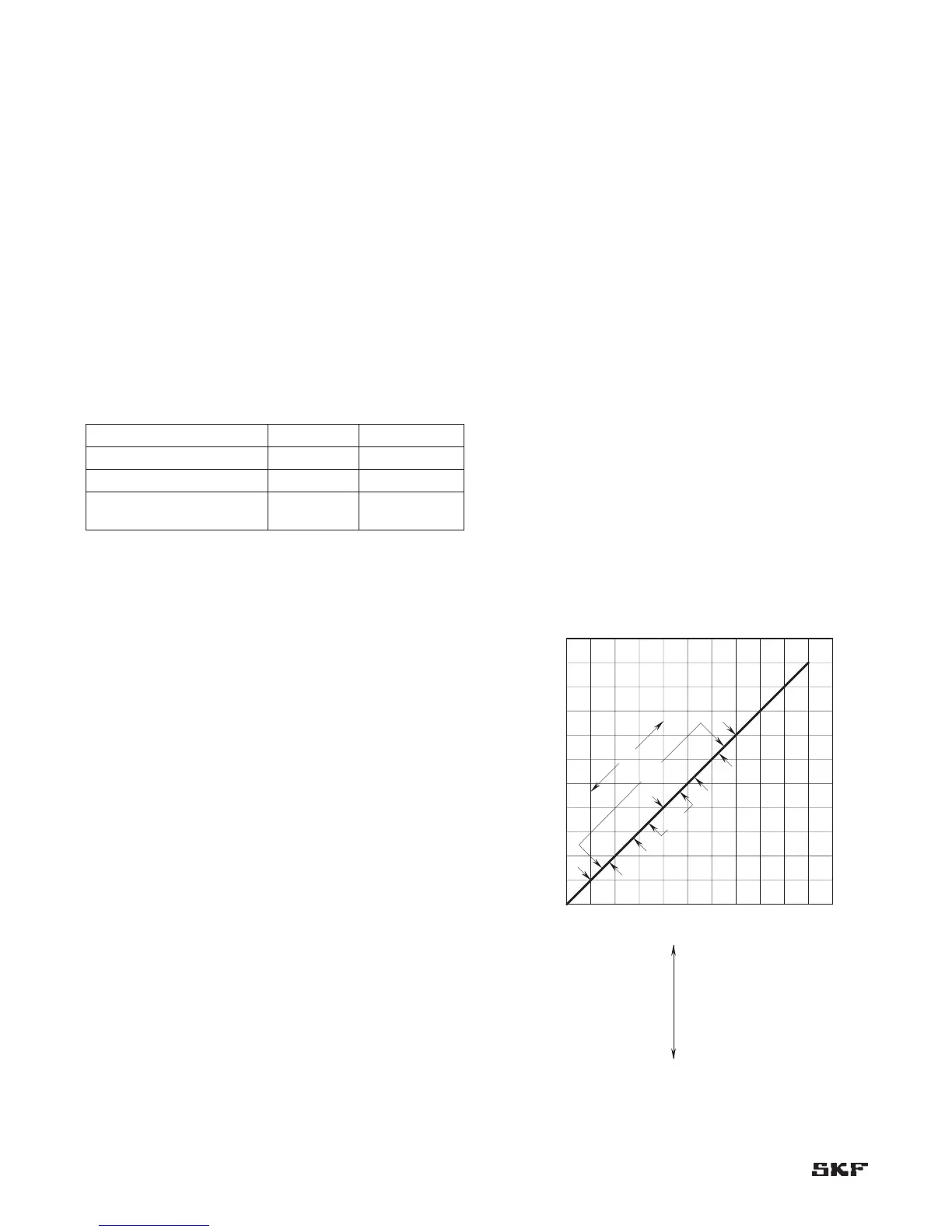
Documentation
After correctly positioning the probe, always record the
probe setting, float zone, normal and counter direction
of thrust, and probe location as shown in Figure 3-16.
Keep this information with all other records of the system
installation.
Figure 3-16. Documentation of thrust-position probe.