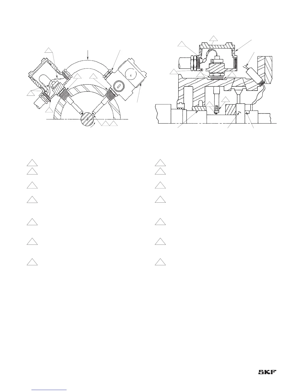
Bearing housing mounting
Figure 2-10. End view.
Notes:
1 Drill and tap housing for 3/4” (19 mm) NPT (typical).
2 Set sealing adapter tight in bearing housing before
pulling lead wires.
3 Identify leads prior to installation. Use tag numbers
as required.
4 Probes must be mounted perpendicular to shaft.
5 Do not pull thermocouple wire and probe lead wires
into same outlet.
6 Check gap volts after CMSS 911 assembly has been
installed. Set gap at -8.0” ±1/2 volts (40 ±2.5 mils
[1 mm ±0.06 mm]).
7 Torque mating connectors to 145 ±5 inch-ounces
(1.02 ±0.035 N-m). Wrap connectors with teflon
tape (typical).
8 Drill 1/4” drain hole at lowest point of box (typical).
Rotation
1 2
4
6
3 Typical
8
7
1/2” Flex Conduit “Sealtite”
or Equivalent (Typical) 3/4”–1/2” Reduction
Bushing (Typical)
CMSS 911 Extension
(Use As Required)
Figure 2-11. Side view.
Notes:
1 Drill and tap housing for 3/4” (19 mm) NPT (typical).
2 Set sealing adapter tight in bearing housing before
pulling lead wires.
3 Identify leads prior to installation. Use tag numbers
as required.
4 Probes must be mounted perpendicular to shaft.
5 Do not pull thermocouple wire and probe lead wires
into same outlet.
6 Check gap volts after CMSS 911 assembly has been
installed. Set gap at -8.0” ±1/2 volts (40 ±2.5 mils
[1 mm ±0.06 mm]).
7 Torque mating connectors to 145 ±5 inch-ounces
(1.02 ±0.035 N-m). Wrap connectors with teflon
tape (typical).
8 Drill 1/4” drain hole at lowest point of box (typical).
CMSS 911 Assembly (Typical)
Radial Bearing
Thrust Collar Thrust Bearing
7
4
6
1
3
2
8
Thermocouple
Wire
Section 2 – Typical eddy probe arrangement plans
2-4