Section 4 – Driver installation
4-3
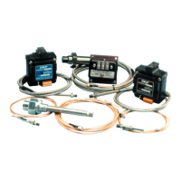
Figure 4-4 shows the electrical and signal
connections for the CMSS 665, CMSS 665P,
CMSS 668 and CMSS 668P Eddy Probe
Drivers.
Note: The power and signal terminal block
(Part number 10818407 for the CMSS
665 and CMSS 668) can be plugged
onto the mating pins two different ways
(depending upon where the cables are
routed). This plug is fail-proof because
you cannot accidentally damage the
driver by plugging it in backwards. A
permanently affixed connector option
(CMSS 665P and CMSS 668P) is also
available and is mainly utilized in hostile
environments.
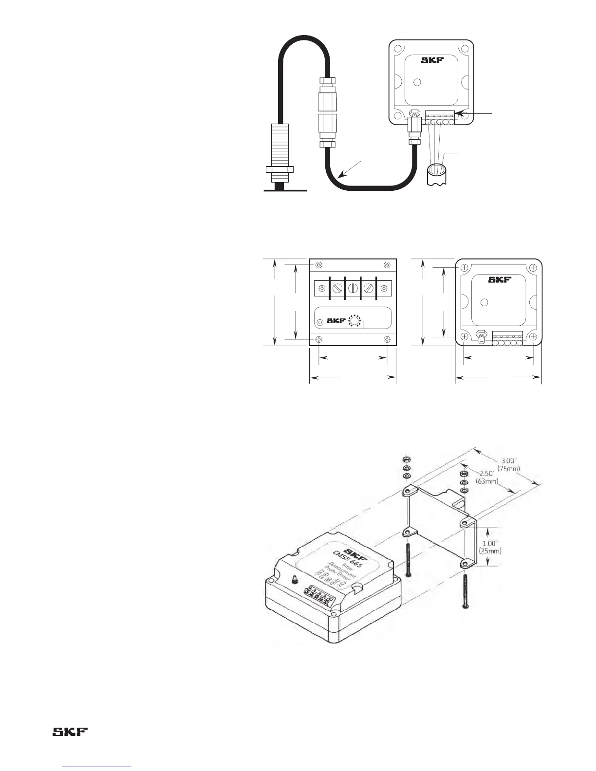
Mounting (Mechanical)
SKF drivers can be directly mounted on any
stable surface like a wall or panel, through the
four mounting holes. For the CMSS 600,
CMSS 606 and CMSS 620-2 Series, a special
isolation plate and non-metallic screws are
required to maintain driver/system isolation.
See figure 4-7. For the CMSS 665,
CMSS 665P, CMSS 668, and CMSS 668P
Series, there is no special isolation plate
required as the driver housings themselves are
non-conductive and therefore keep all circuits
isolated. For the CMSS 665, CMSS 665P,
CMSS 668, and CMSS 668P Series in order
to conserve space, use ordinary steel DIN-rails
(available from SKF and most electrical supply
outlets) and the DIN-rail boot or clip (available
from SKF). See figures 4-6 and 4-8.
Note: CMSS 600, CMSS 606, and CMSS 620-2
Drivers can not use DIN-mounts.
Figure 4-5 shows the driver dimensions.
Figure 4-6 shows the DIN-mount boot (clip).
Figure 4-4. Electrical and signal connections for probe drivers (CMSS 665,
CMSS 665P, CMSS 668 and CMSS 668P).