Section 3 – Probe installation
3-5
Probe Adapter
Figure 3-9. Probe Adapter.
Installation instructions for
CMSS 911 Probe Holder with
Housing and CMSS 911 Dual
Sensor Holder
1. Cut thread extension part 7 or (part 11) to desired
length if necessary, deburr, and chase threads using a
1/4–28 or 3/8–24 tap.
Caution: The probe must turn freely. Forcing the probe
can destroy both the probe and the holder.
2. Push connector through threaded extension 7 or
(11) from small end, apply Loc-Tite, screw probe into
extension to desired length and lock in place with jam
nut 8 or (7).
3. Thread probe adapter union 4 or (5) into 3/4” (19 mm)
NPT machine case. Tighten firmly.
4. Attach outlet body 1 or (3) to probe adapter union 4 or
(5) and tighten.
5. Thread probe holder through probe adapter union until
probe tip is gapped at 0.040” (1 mm) or the driver
output reads -8 Vdc. (There must be -24 Vdc applied
to the driver.)
6. Slide probe adapter collar 5 and 6 or (8 and 9) over
the probe holder and tighten hex screw 6 or (10). This
locks the probe and holder into place.
7. Screw outlet body cover (1) into the outlet body
extension 2 and tighten.
8. Connect conduit to outlet body 1 or (3) and plug extra
conduit entries.
CMSS 65 Probe Tip Assembly
Part Number CMSS 30221900
Probe Adapter 3/8-24 to 1/4-28 used
when installing CMSS 65 Probes in
Probe Holder with 3/8-24 threads.
CMSS 912 Dual Axial Probe
Adapter
The CMSS 912 Dual Axial Probe Adapter provides
mounting and protection for two parallel probes for
measuring axial thrust position. The probes are mounted
on adapters which are installed directly on the machine
case through 1/2” (12.7 mm) NPT threaded holes. The
adapters provide for easy gapping of the probes. The
enclosure bolts directly to the machine case and protects
the probe installation. A removable cover provides access
to the installed probe.
It is recommended that probes be ordered with a case
length of 1.2 inches and an overall length of 0.5 or 1.0
meters.
Table 3-1.
Model
number
Working range * Probe thread
CMSS 912-1
1.10” to 2.35”
(28 mm to 60 mm)
1/4-28 CMSS 61/CMSS 65
CMSS 912-3
0.75” to 2.00”
(19 mm to 51 mm)
3/8-24 CMSS 60/CMSS 68
CMSS 912-4
0.95” to 5.00”
(24 mm to 127 mm)
3/8-24 CMSS 60/CMSS 68
* Working range with field trim of probe holder.
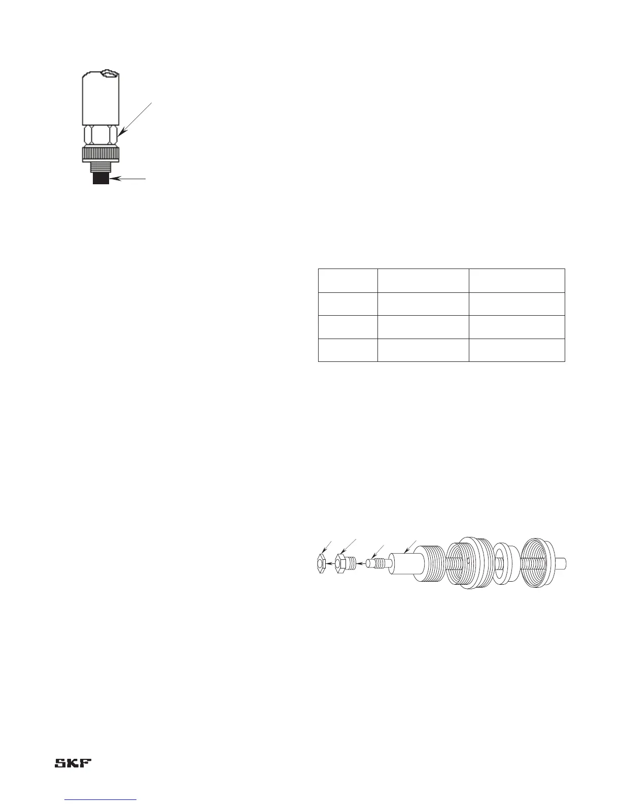
CMSS 61/CMSS 65 Eddy Probe unique installations
The connector body (0.28”) is larger than the 1/4–24 hole.
Take the connector apart, slide the cable and nut through
the stinger, and then reassemble the connector. Refer to
section on connectors for detailed explanation.
Requires the CMSS 912 with a 3/8–24 stinger and a
3/8–24 to 1/4–28 adapter nut (the CMSS 65 connector will
not fit through the 1/4–24 stinger). See Figure 3-10.
Figure 3-10. Adapter used for mounting CMSS 65 Probes.
Probe
Stinger
Jam Nut
Adapter Nut
(3/8-24 to
1/4-28)