Section 3 – Probe installation
3-6
Installation instructions for CMSS 912 Dual Axial Probe Adapter
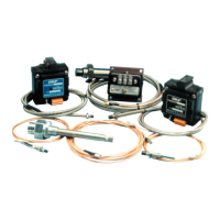
1. Prepare the mounting surface as
shown in Figure 3-11.
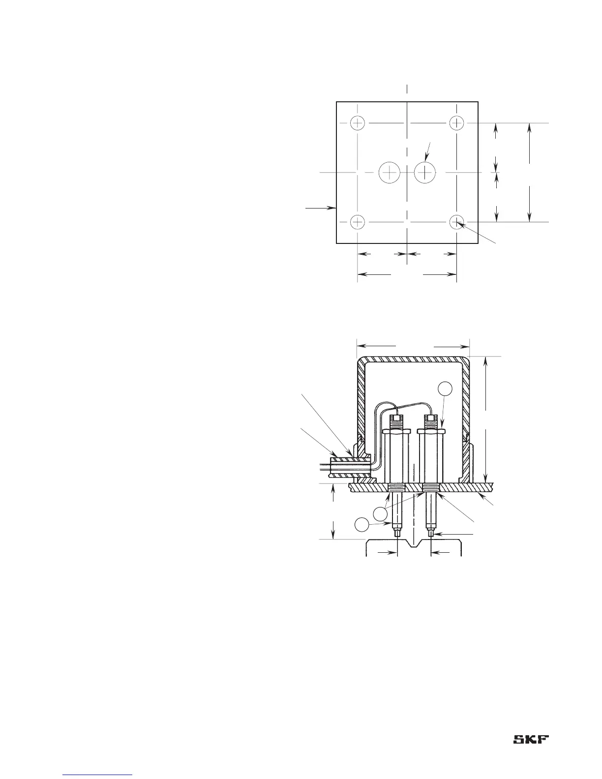
2. Cut threaded extension (Part 2)
Figure 3-12 to desired length,
deburr, and chase the threads with
a tap.
3. Thread probe connector through
threaded extension (2) from small
end and screw probe into extension
to desired length. Lock in place with
lock nut (1).
4. Thread fitting (3) into 1/2”
(12.7 mm) NPT hole in machine
case.
5. Thread assembled unit through
fitting until the probe tip is gapped
at approximately 0.040” (1.0 mm)
or the driver output reads -8 Vdc.
Note: To oil-proof a CMSS 912
Probe Adapter, apply Loc-Tite
pipe thread sealant liberally
to both pipe threads and
machine threads of probe
holder during installation.
This is good for temperatures
from -65 to +300 °F (-18
to +149 °C). Cure time is
48 hours, but this can be
accelerated significantly using
Loc-Tite “Klean N’ Prime” or
Loc-Tite “Locquic Primer NF.”
6. Tighten the jam nut (1) on the
extension when probe is properly
gapped.
7. Install CMSS 912 housing on
machine.