Section 2 – Typical eddy probe arrangement plans
2-3
Radial shaft vibration probes
Referenced such that when viewed from the driver end of
the machine train, the Y (vertical) probe is on the left side
of the vertical center, and the X (horizontal) probe is on the
right side of the vertical center regardless of the direction
of shaft rotation.
Bearing cap mounting
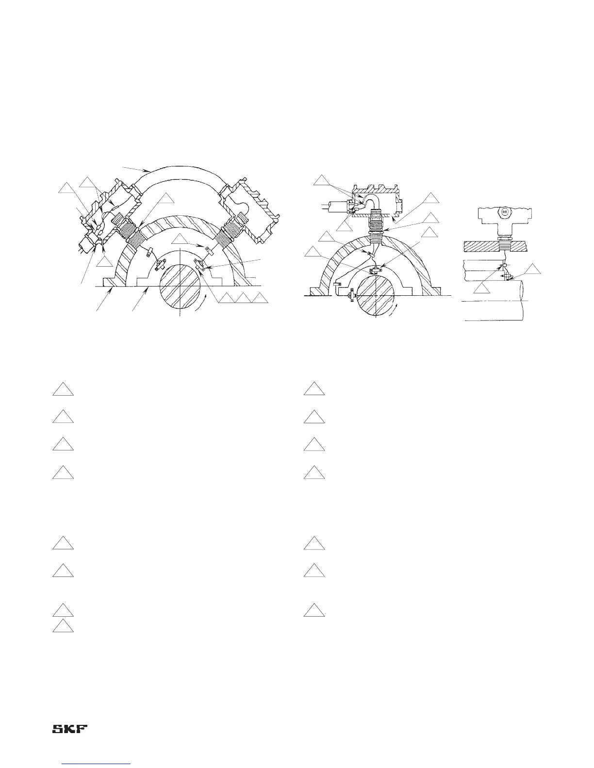
Figure 2-7. End view (preferred).
Notes:
1 Set sealing adapter tight in bearing housing before
pulling lead wires.
2 Probe lead wires must be secured against internal
whipping and rubbing.
3 Identify leads prior to installation. Use tag numbers
as required.
4 Probes must be mounted perpendicular to shaft.
5 Do not pull thermocouple wire and probe lead wires
into same outlet without engineering department
approval.
6 Set gap volts after assembly has been installed.
7 Set gap at -8.0 ±1/2 volt (example: 40 ±2.5 mils
[1 mm ±0.06 mm]).
8 Torque mating connectors to 145 ±5 inch-ounces
(1.02 ±0.035 N-m). Wrap connectors with teflon
tape.
9 Drill 1/4” drain hole at lowest point of box (typical).
10 Preferred arrangement for probe installation:
Viewed from the driver end of the machine train,
the Y-probe (vertical) shall be to the left of vertical
center. The X-probe (horizontal) shall be to the right
of vertical center.
Figure 2-8. End view (alternate). Figure 2-9. Side view.
Notes:
1 Set sealing adapter tight in bearing housing before
pulling lead wires.
2 Probe lead wires must be secured against internal
whipping and rubbing.
3 Identify leads prior to installation. Use tag numbers
as required.
4 Probes must be mounted perpendicular to shaft.
5 Do not pull thermocouple wire and probe lead wires
into same outlet without Engineering Department
approval.
6 Set gap volts after assembly has been installed.
7 Set gap at -8.0 ±1/2 volt (example: 40 ±2.5 mils
[1 mm ±0.06 mm]).
8 Torque mating connectors to 145 ±5 inch-ounces
(1.02 ±0.035 N-m). Wrap connectors with teflon
tape.
9 Drill 1/4” drain hole at lowest point of box (typical).
10 Preferred arrangement for probe installation:
Viewed from the driver end of the machine train,
the Y-probe (vertical) shall be to the left of vertical
center. The X-probe (horizontal) shall be to the right
of vertical center.