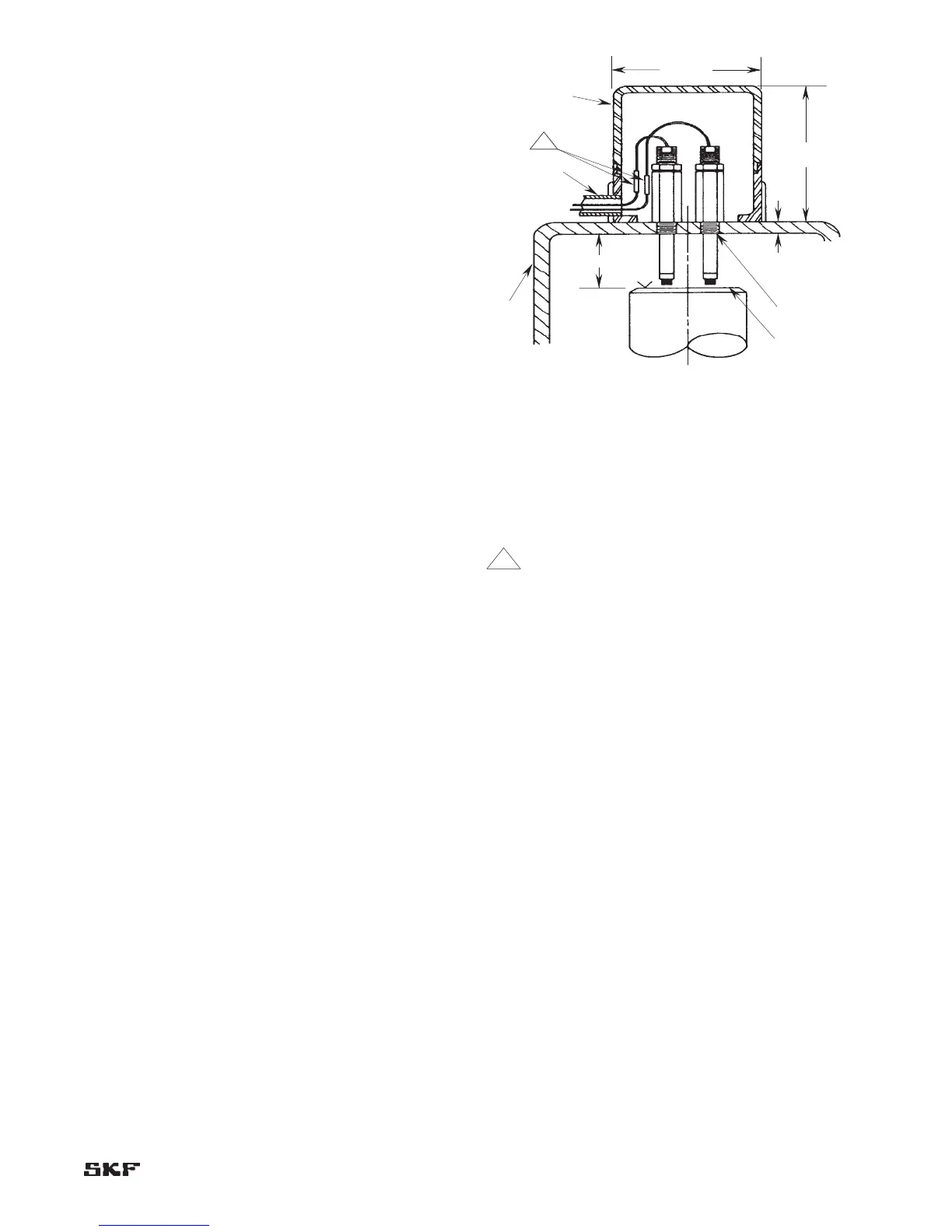
Axial probe installation
Axial probe installation recommendations
At least two probes per rotor are recommended.1.
Where the probes cannot be changed without shutting 2.
down the machine, install spare probes
Calibrate probe, cable and driver and record final 3.
response curves for primary as well as spare probes.
The SKF CMSS 601 Series Static Calibrator may be
used.
Try to observe the thrust collar with one probe and the 4.
shaft with the other.
Probes must be mounted within one foot of the thrust 5.
collar.
Avoid mounting probes through thin plates or bell 6.
housings that may bow with thermal expansion.
Determine the float zone of the rotor by jacking the 7.
rotor in both directions.
Measure and compare the rotor movement with dial 8.
indicators on the shaft, the eddy probe voltage change
at the driver and the monitor reading. (All three
should agree.)
Jack the shaft several times each way to verify 9.
readings.
Set the probe gap so the center of the probe’s range is 10.
in the center of the float zone.
Securely lock the probe and any adapters in place.11.
Be sure the probe tip has a side clearance of at least 12.
half the probe diameter.
Figure 2-12.
Notes:
1 Set sealing adapter tight in housing before pulling
lead wires through.
2 Probe lead wires must be secured against internal
whipping and rubbing.
3 Identify probe leads prior to installation. Use tag
numbers as required.
4 Probes must be mounted perpendicular to shaft or
surface it is “seeing”.
5 Do not pull thermocouple wires and probe lead wires
into same outlet.
6 Check gap volts after CMSS 911 or CMSS 912
assemblies have been installed.
7 Set gap at midpoint of probe range at the center of
the shaft float zone.
8 Torque mating connectors to 145 ±5 inch-ounces
(1.02 ±0.035 N-m). Then wrap connectors with
teflon tape.