CMSS 601-8 Field Calibrator
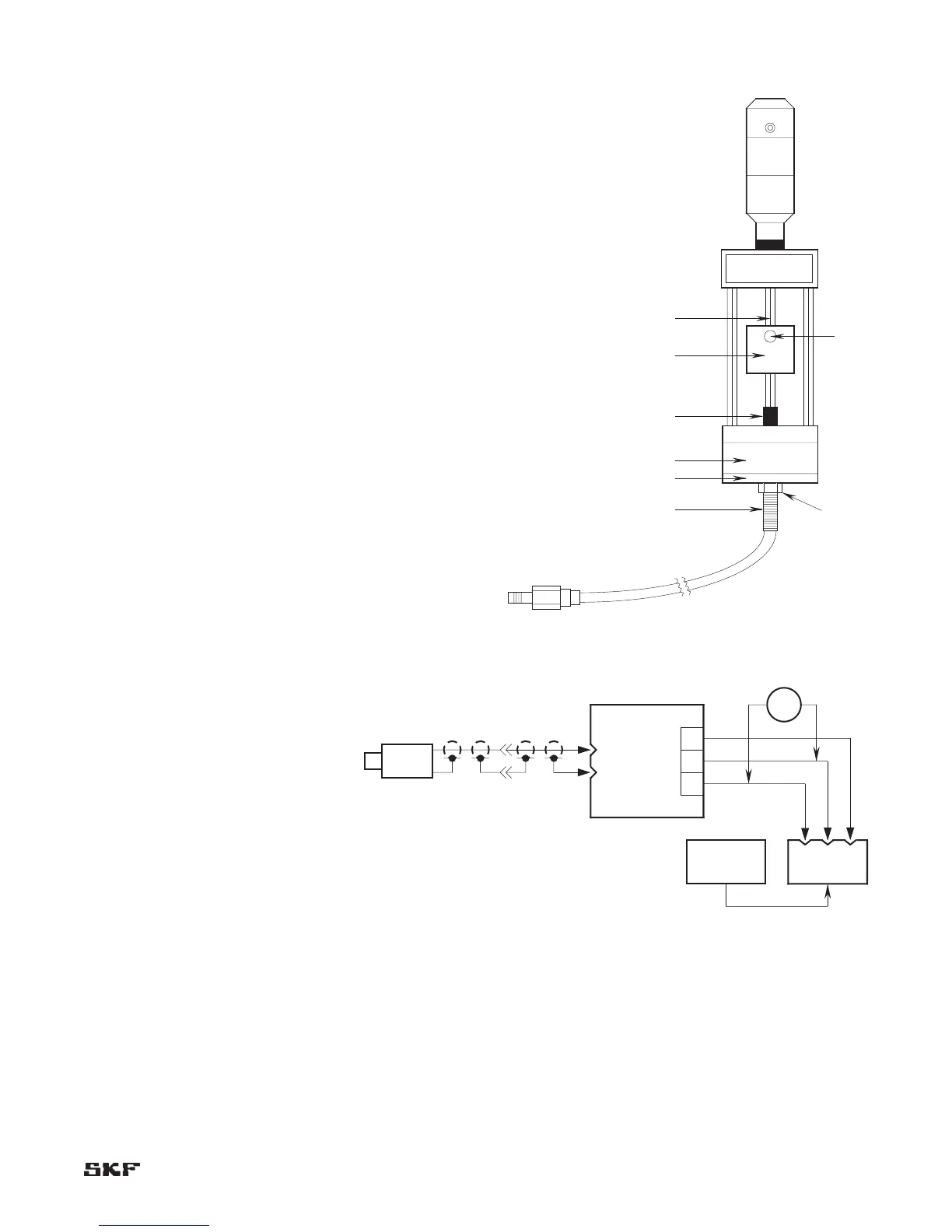
Set-up procedure (Figure 6-3)
Slip the small target A, onto the micrometer shaft B, 1.
and lock into place with set screw C.
Screw the appropriate disc-shaped probe adapter D, 2.
onto the probe E. There is one disk adapter for the
CMSS 60/CMSS 65 Probes and one for the CMSS 61/
CMSS 68 Probes.
Insert probe tip carefully through center hole in magnet 3.
F, until adapter clamps to magnet. Align adapter
circumference with magnet circumference.
Turn the micrometer spindle to 40 mils (1 mm) position 4.
and screw the probe into the calibrator assembly (allow
cable to turn freely and not twist) until probe tip is
about 40 mils (1 mm) from target.
Connect the probe lead to the appropriate CMSS 900 or 5.
CMSS 958 Extension Cable and connect the extension
cable to the appropriate probe driver (CMSS 600 Driver
for CMSS 60 Series Probes, CMSS 606 Driver for
CMSS 61 Series Probes, CMSS 665 Driver for CMSS 65
Series Probes, CMSS 668 Driver for CMSS 68 Series
Probes).
Apply -24 Vdc power to the driver, and connect a 6.
voltmeter to the driver output (Figure 6-4).
Check that the micrometer is set to 40 mils (1 mm). 7.
Turn probe to get a reading of -8 V on the voltmeter
(without disturbing the 40 mils (1 mm) reading on the
micrometer) and tighten lock nut G.
Proceed with calibration procedure 8.
on page 6-4.
Figure 6-3. CMSS 601-8 Model Field Calibrator shown.