Section 3 – Probe installation
3-9
Cables and
connections
The probe and driver are always
interconnected with the CMSS 900
or CMSS 958 Extension Cable which
is specifically manufactured to have
the proper electrical characteristics.
Any reference to cable length is to its
electrical length and not its physical
length.
When threading the probe through a
tapped hole, disconnect the extension
cable and rotate the probe cable with
the probe to minimize twisting. The
probe and cable are manufactured for
1.0 meter length to help in installation
(especially in tight areas).
Caution: Excessive twisting can
eventually cause damage to
the cable.
Wrap the connectors with insulating
tape or heat shrink sleeving to reduce
ground loop problems (isolate from
ground). Plumber’s teflon tape is best
because it is oil-proof and meets the
electrical requirements. Taping is also
extremely important in hazardous
locations to prevent sparks if the cable
and connector “whip around” during
normal operation.
Avoid tight bends (any bend that
exceeds the natural bending radius of
the cable) in the installed interconnect
cable. Tight bends can induce noise
and cause undue cable wear.
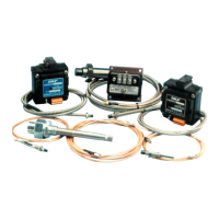
Cabling should be tied down (Figure
3-17) about 6” to no more than 10”
(152 to 254 mm) from the probe to
prevent undesired movement of the
cable which is also a source of noise
and wear.
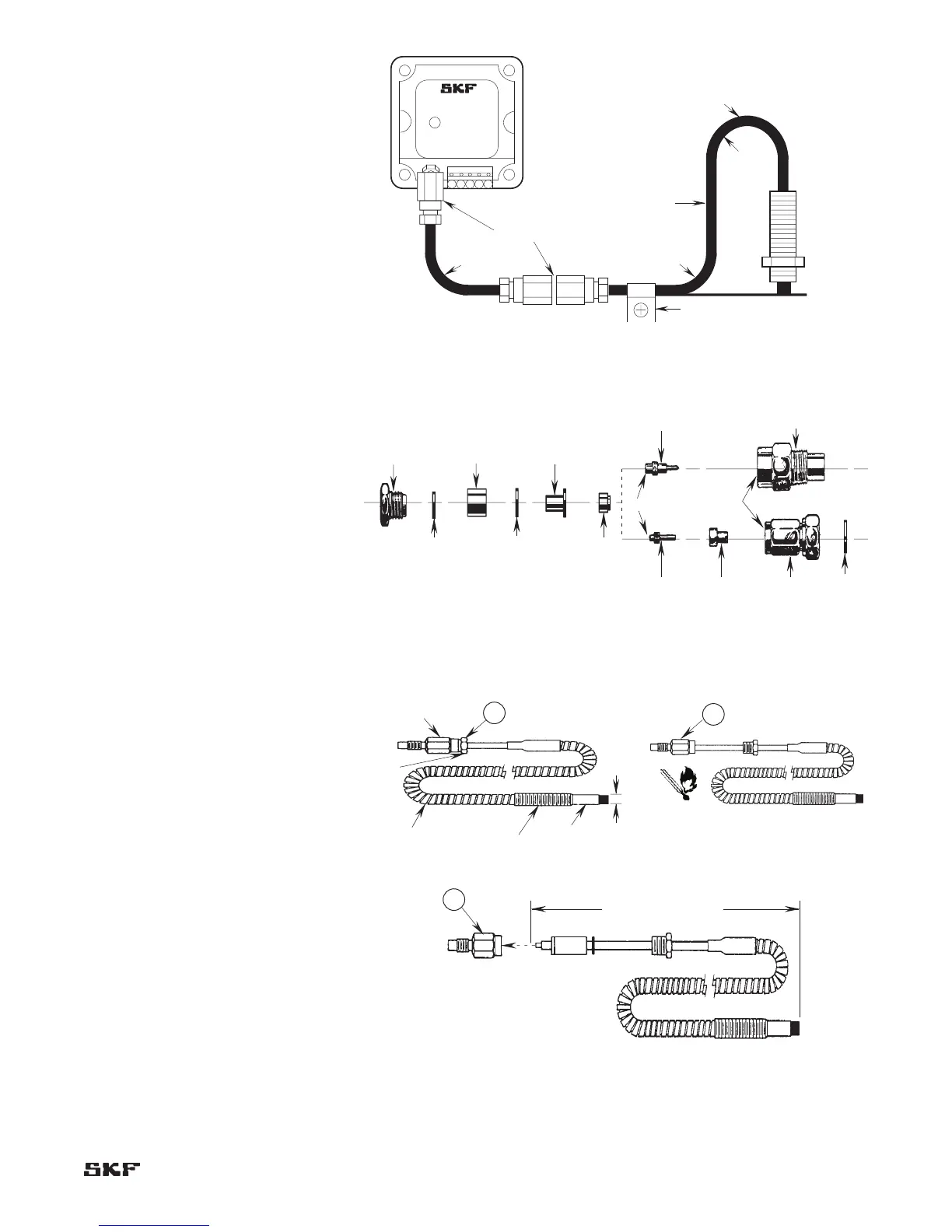
Figure 3-18 shows the different parts
of a connector.
Figure 3-19 shows how to disassemble
the CMSS 61/CMSS 65 connector.
Figure 3-17. Probe cable tie-down requirements.