Mounting the probe
SKF makes four types of mounting brackets for eddy
probes.
CMSS 904 Probe Holder•
CMSS 911 Probe Holder with housing•
CMSS 912 Dual Axial Probe Adapter•
CMSS 903 Series Mounting Brackets•
Electrical output of the eddy current probe which is due
to vibration of the probe itself is not distinguishable from
output due to vibration of the observed surface. Therefore,
the eddy probe must be mounted rigidly to prevent it from
vibrating.
Probes can be mounted by threading it through a hole
in an existing part of a machine, such as the casing, or
by using a special mounting bracket. The probe must be
firmly locked in place with a jam nut. See Figures 3-3 and
3-4.
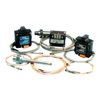
Figure 3-3. Probe mounting through casing.
Probes must not be installed closer than the ratio of
half the probe tip diameter to a shaft shoulder or other
discontinuity. Otherwise, probe target calibration will be
altered. This clearance must also be maintained with all
stationary components so that the entire electric field is
concentrated on the observed surface only. If necessary,
surfaces should be chamfered.
Back the probe locknut off of the probe and over the probe
lead. Thread the probe into the bracket or clip (tip first)
taking care not to damage the probe or target surface.
Turn the probe clockwise until the tip is within 0.125”
(3 mm) of the shaft. Do not use probe lead to thread
probe into place (turn the probe case). With the extension
cable connected between the probe and driver, set the gap
at mid-range (approximately: -8 Vdc for CMSS 61 and
CMSS 65; -10 Vdc for CMSS 60 and CMSS 68; -9 Vdc for
CMSS 62). Tighten the cap screws or locknut, depending
upon the mount type, then recheck the gap.
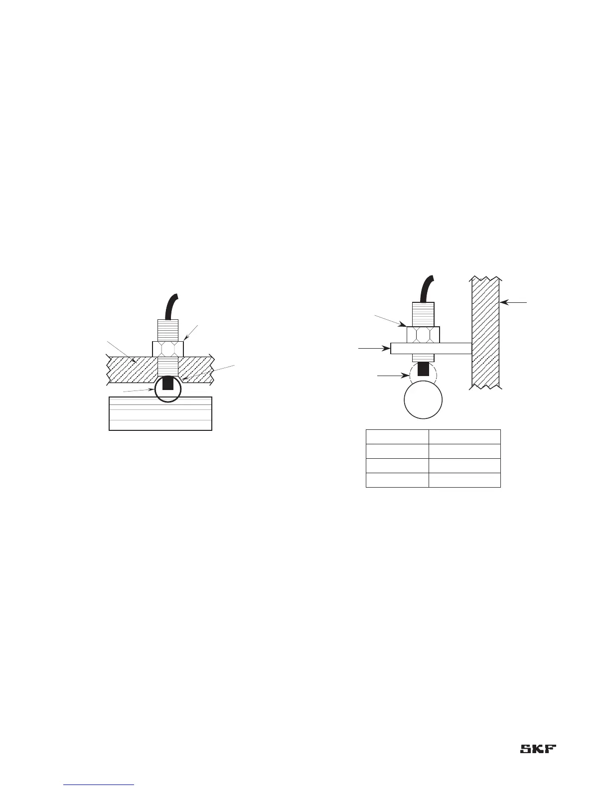
Figure 3-4. Probe mounting on bracket.