If slight adjustment of the slope is necessary to calibrate 3.
to a particular shaft material, the CALIB (calibrate)
control on the eddy probe driver unit provides a ±10%
adjustment for sensitivity.
Note: After a driver unit is calibrated, any probe (of the
proper model number) and any extension cable may
be substituted without recalibration, and maintain an
accuracy of ±5%.
Figure 6-6. Location of calibration (Slope) adjusting potentiometer.
Calibration procedure
Slowly adjust the micrometer dial, first increasing and 1.
then decreasing from the 40 mil (1 mm) starting gap,
and record the new voltmeter readings for each 5 mil
(125 µm) increment.
Note: Contact is not necessarily zero volts, since the gap is
measured from the coil within the tip, and not from
the surface of the tip itself. The distance from the coil
to the tip surface varies ±3 milli-inches. Ordinarily,
the first 10 or 12 milli-inches of gap is not usable.
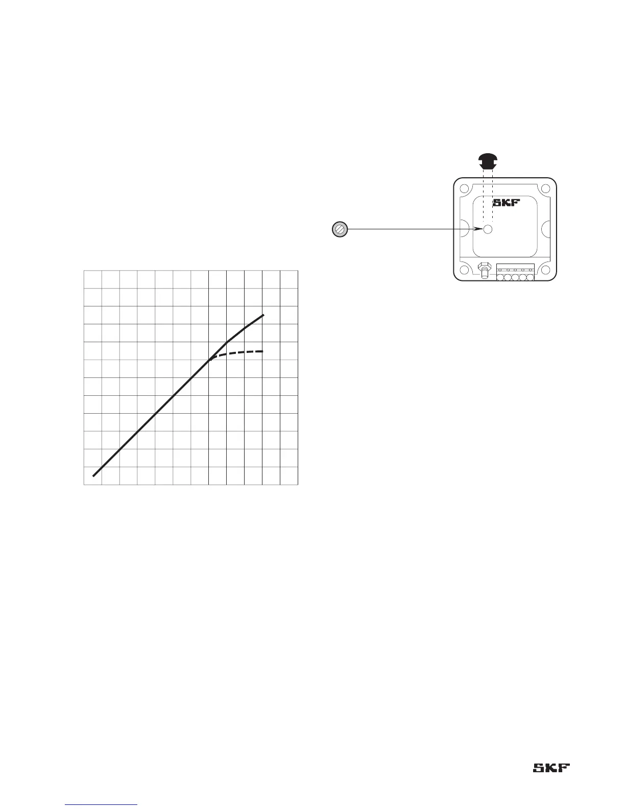
Plot a straight-line graph through the recorded points. 2.
A probe that is in calibration should have a graph with
a 200 mV/mil (8 mV/µm) slope. Each volt equals five
milli-inches (125 µm), as shown in Figure 6-5.
Figure 6-5. Typical response curve.
24
22
20
18
16
14
Eddy Probe Gap: Millimeters
Eddy Probe Gap: Milli-Inches
Output Volts DC
12
10
8
6
4
2
0 10 20 30 40 50 60 70 80 90 100 110 120
0 .25 .50 .75 1.0 1.25 1.5 1.75 2.0 2.25 2.5 2.75 3.0