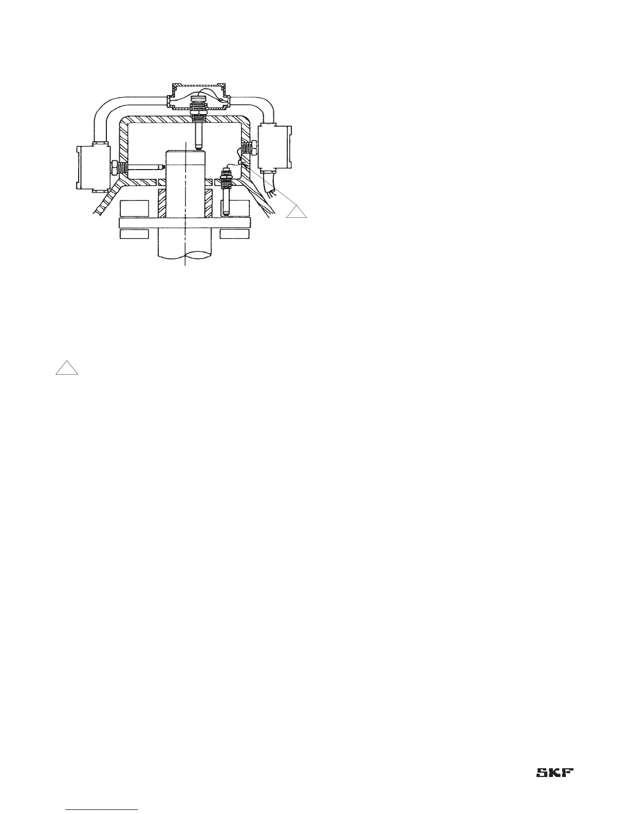
Figure 2-13.
Notes:
1 Set sealing adapter tight in housing before pulling
lead wires through.
2 Probe lead wires must be secured against internal
whipping and rubbing.
3 Identify probe leads prior to installation. Use tag
numbers as required.
4 Probes must be mounted perpendicular to shaft or
surface it is “seeing”.
5 Do not pull thermocouple wires and probe lead wires
into same outlet.
6 Check gap volts after CMSS 911 or CMSS 912
assemblies have been installed.
7 Set gap at midpoint of probe range at the center of
the shaft float zone.
8 Torque mating connectors to 145 ±5 inch-ounces
(1.02 ±0.035 N-m). Then wrap connectors with
teflon tape.