The drivers can be mounted inside the housing on ordinary
steel “Type C DIN-rails” available from SKF. There are
two sizes, 9” (225 mm) and 15” (375 mm) lengths. Use
part number CMSS 31093101 and CMSS 31093100
respectively.
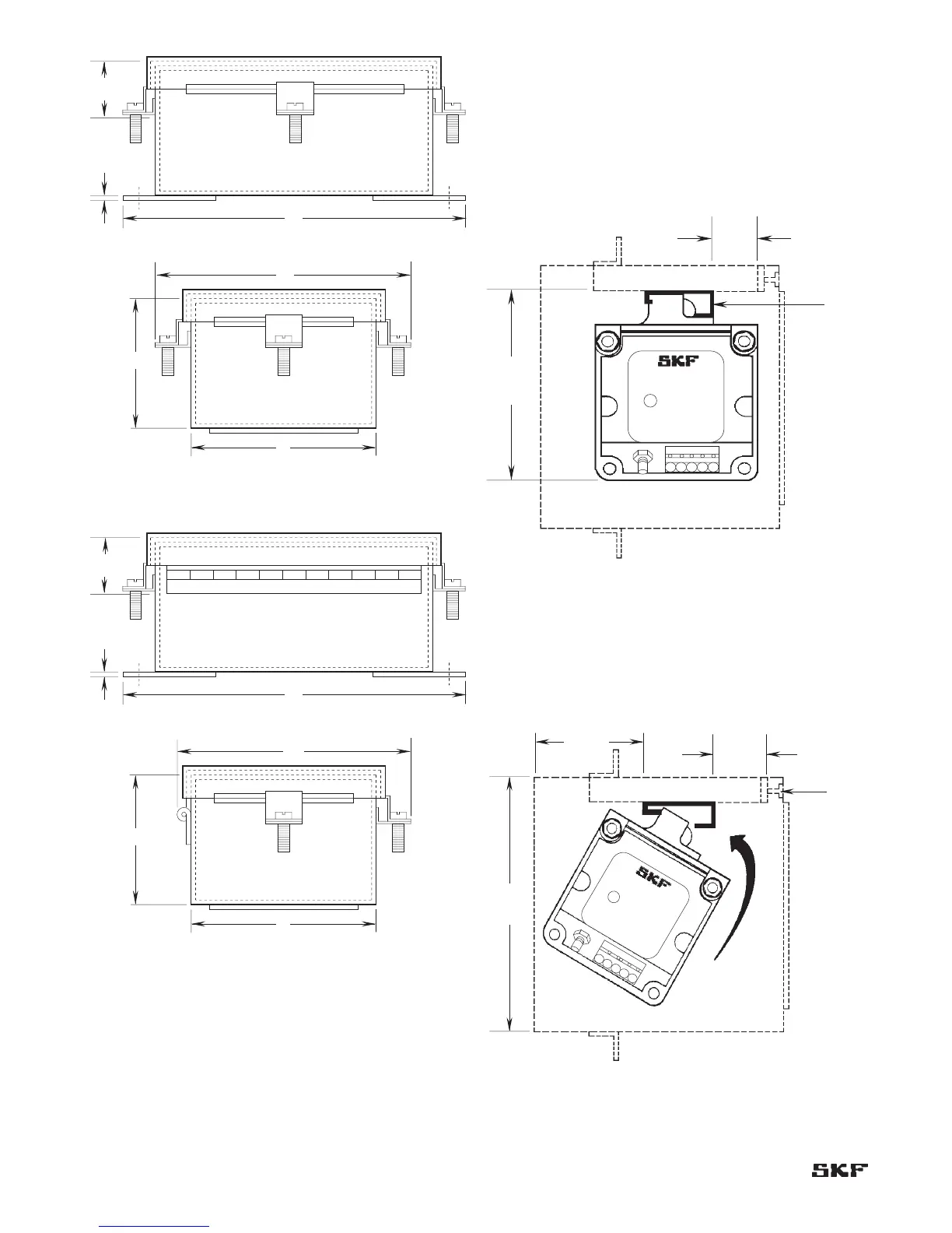
Figure 4-12 shows how to install the drivers using the
DIN-rail and clip.
Figure 4-12. Installation of drivers in recommended weatherproof
housings.
Figure 4-13 shows the minimum clearances needed
to install the drivers in weatherproof housings. These
clearances allow for the cables and for the “swing” involved
in snapping the driver clip into the DIN-rail.
Figure 4-13. Minimum clearances needed to install drivers in
weatherproof housings.
Figure 4-11. Hinge style weatherproof housing dimensions.
 Loading...