3
- 27 -
951-171-049
Version 02
EN
3. Overview, functional description
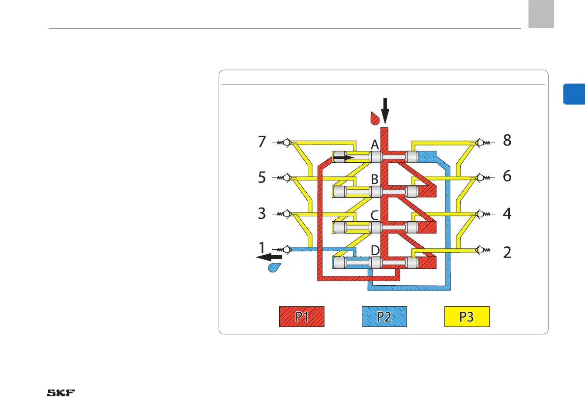
Fig. 10 Course of the lubricant in the metering device phase 5
E
Phase 5
When piston D reaches its left end position,
it opens the connection duct to the right end
of piston A. As a consequence lubricant P1
supplied by the pump flows to the right end
of piston A and piston A moves to its left end
position. By doing so the corresponding lu-
bricant volume P2 is displaced to outlet 1.
Phases 6 - 8
In Phases 6 to 8 the lubricant movement
follows the same principle as in phases 1 to
5 and lubricant is supplied from the outlets
8, 6 and 7 (phases 6, 7 and 8). If the sup-
ply continues after phase 8, the cycle starts
from the beginning again.

 Loading...