Phase 7
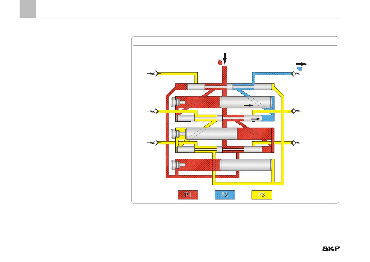
Control piston A2 has reached its right end
position. Thereby it opens the connection
duct to the left end of control piston B2 and
metering piston B1. The pressurized lubri-
cant P1 is now located at the left end of con-
trol piston B2 and metering piston B1. Due
to its larger cross-section lubricant P1 first
moves metering piston B1 to the right and
then displaces the lubricant enclosed on the
right side of metering piston B1 to outlet 5.
Phase 8
As soon as metering piston B1 reaches its
right end position, the pressurized lubricant
P1 moves the control piston A2 (black ar-
row) rightward and additionally displaces
the enclosed lubricant in front of control
piston C2 to outlet 5.
The total output of outlet 5 corresponds to
the output of metering piston B1 and con-
trol piston B2.

 Loading...